Review
. 2025 Jun 19:52:634-667.
doi: 10.1016/j.bioactmat.2025.06.014. eCollection 2025 Oct.

Bidirectional mechanisms and emerging strategies for implantable bioelectronic interfaces

Affiliations
Review

Bidirectional mechanisms and emerging strategies for implantable bioelectronic interfaces

Zineng Yan et al. Bioact Mater. .

Abstract

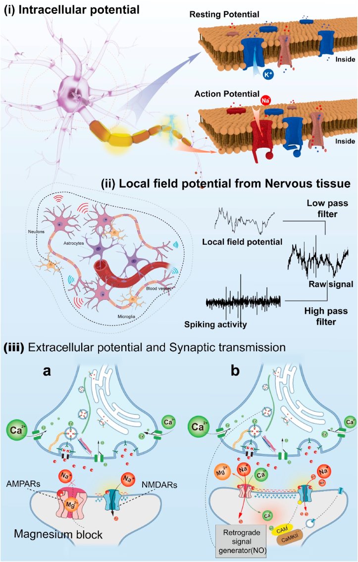
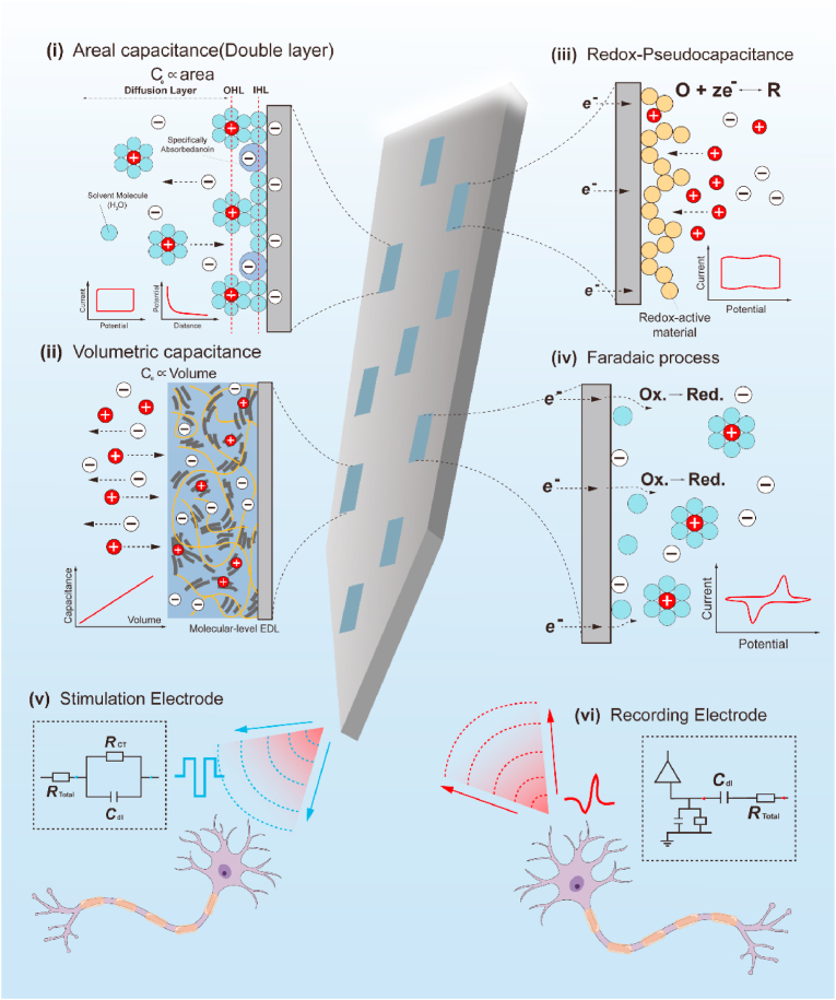
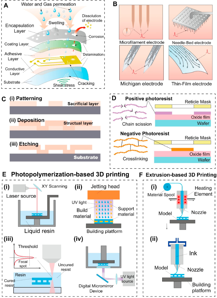
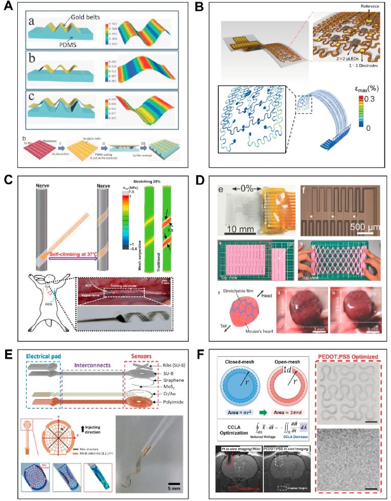
Neural network functionality depends on the signaling of excitable cells and intricate synaptic connections, which collectively promote advanced functions of the brain, such as perception, motor control, and cognition. Neurological diseases may cause changes in the structure and connection patterns of neural networks, thereby leading to loss of motor and sensory functions. Neural interfaces are dependable tools for recording or stimulating neural circuit dynamics, but conventional neural implants do not align with the physicochemical characteristics of living tissues, resulting in eventual failure of these interface devices. These challenges in neuroengineering have spurred progress in materials science. In this account, we explore the interaction mechanisms between electrodes and biological tissues, offering strategies to meet the electrochemical and biocompatibility demands of bioelectronic interfaces in engineering, with an emphasis on the structural design and manufacturing technologies of implantable devices.

Keywords: Nanostructures; Neural implantable device; Neural interface; Neural probe design.


Conflict of interest statement

The authors declare the following personal relationships which may be considered as potential competing interests: Changmao Ni and Li Huang are currently employed by Wuhan Neuracom Technology Development Co., Ltd.

Figures

Image 1
Graphical abstract
Fig. 1
Fig. 1
Transmission of electrophysiological signals in neural tissue: (i) Generation of intracellular potentials and corresponding electric fields. The high permeability of the cell membrane to K+ ions, along with active transport by sodium‒potassium pumps, maintains the ionic gradient inside and outside the cell in the resting state. When stimulated, the cell experiences a rapid and transient reversal of the membrane potential. After the peak is reached, the K+ channels open, causing the membrane potential to decrease. Eventually, the sodium‒potassium pump restores the ion distribution, bringing the membrane potential back to the resting level. (ii) Electric field coupling of neural tissue and the LFP (black dashed line). (iii) Generation of extracellular potentials and their corresponding electric fields. Electrical activity at synaptic sites, APs that erupt in the initial segment of the axon, and calcium spikes are critical components of extracellular potentials. The transport regulatory processes of AMPA receptors and NMDA receptors within neurons dictate their dynamic changes at the postsynaptic membrane, serving as a crucial prerequisite for synaptic plasticity.
Fig. 2
Fig. 2
Different types of charge transfer mechanisms at electrode–tissue interfaces: (i) Charge transfer process related to the area capacitance. The capacitance is proportional to the area of the surface electric Double Layer (EDL). When the electrode contacts the electrolyte, the charges on the electrode surface attract or repel the charge carriers within the electrolyte, resulting in the formation of two charge layers between the electrode and the electrolyte. The first layer is the dense layer, which consists of solvent molecules and solvated ions. The second layer is the diffusion layer, which is situated on the outer side of the electrode, where the ion concentration progressively decreases. OHP is Outer Helmholtz Plane. IHP is Inner Helmholtz Plane. (ii) Charge transfer process related to the volumetric capacitance. The capacitance depends on the formation of an EDL at the molecular level and is proportional to the electrode volume (using PEDOT:PSS as an example, with PSS fibers depicted in brownish-yellow and PEDOT in dark gray). (iii) Pseudocapacitance induced by a reversible Faradaic process. Charge transfer occurs near the material, with ions being electrochemically adsorbed, which decreases the diffusion distance. O and R denote the oxidized and reduced states of the redox pair, respectively. (iv) Charge is introduced into the biological system via an irreversible Faradaic redox process. The kinetics of the redox reaction are slow relative to the mass transfer and cannot keep up with it. (v) Neural stimulation electrode and its equivalent circuit. When the total charge injected is sufficiently small, all the charge enters the double-layer branch. With increasing charge injection density, charge starts to flow into the parallel Faradaic branch. Rtotal is the resistances not directly involved in the interfacial electrochemical reaction of the interface. (vi) Neural recording electrode and its equivalent circuit.
Fig. 3
Fig. 3
Postimplantation injury and failure modes of neural implants. A. Relative interaction of neural implants with brain tissue. B. Key pathophysiological events of secondary injury following implantation. (i) The acute secondary injury process after implantation involves cell death, inflammation, and vascular responses. Microglia, astrocytes, peripheral neutrophils, and macrophages are the initial responders following injury. These cells release a variety of inflammatory factors that induce cell death while removing debris from damaged tissue. The vascular system of the brain is also compromised after implantation, resulting in bleeding, vasospasm, and edema, leading to tissue compression and impacting brain perfusion. (ii) Continued inflammation results in increased vascular permeability, facilitating further recruitment of blood-derived monocytes. Astrocytes undergo proliferation and hypertrophy, with glial scars starting to form and gradually expanding to create a protective layer that prevents the spread of injury. (iii) The neural glial scar gradually matures, with macrophages positioned centrally and microglia migrating around the lesion. Glial scars suppress axonal growth. C. Timeline of the inflammatory response and failure modes of neural implants. D. Proposed mechanisms of micromotion-mediated astrocyte activation. Shear stress activates mechanosensitive ion channels, increasing the flux of Ca2+ (a second messenger), which triggers changes in astrocyte morphology and ECM components to adapt to shear stress, resulting in glial cell proliferation and hypertrophy, along with excessive release of neurotoxic lipids [71]. Adapted with permission. Copyright 2023, John Wiley and Sons. E. Homotrimeric architecture of Piezo1. When subjected to mechanical stimulation, the phospholipid bilayer on the cell surface bends and deforms, altering the angles of the three blades of the Piezo1 ion channel with respect to the central axis, leading to an increased aperture of the central ion-conducting pore; ions are driven into the cell through this pore owing to the concentration gradient of ions inside and outside the cell [79]. Adapted with permission. Copyright 2021, Springer Nature.
Fig. 4
Fig. 4
Technology for fabricating neural implants. A. Neural electrodes are usually composed of three layers: a substrate, a conductive layer, and an encapsulation layer. The moisture-rich environment and the shear stress caused by the tissue micromovement, leading to issues such as corrosion, strain-induced cracking, delamination, and gas‒liquid permeation, can significantly impact the lifespan of electrodes. B. Construction paradigm for neural implants. C. Micro/nanofabrication processes. MEMS fabrication usually consists of growing and patterning a sacrificial layer on a substrate, depositing structural materials using physical or chemical deposition methods, shaping the structural materials through photolithography or etching techniques, and removing the sacrificial layer with suitable wet etchants. D. The photochemical reaction during UV exposure leads to a chemical process in the photoresist film, causing an increase or a decrease in its solubility in the developing solution, thus enabling the creation of a specifically structured photoresist film. E. Photopolymerization-based 3D printing technologies: (i) stereolithography (SLA), (ii) PolyJet, (iii) two-photon polymerization (2 PP), and (iv) digital light projection (DLP). F. Extrusion-Based 3D printing technologies: (i) fused deposition modeling (FDM) and (ii) DIW.
Fig. 5
Fig. 5
Micro/nanofabrication of neural implants. A. Schematic diagram of ultraviolet exposure technology. B. Direct electron beam patterning of electro-optically active PEDOT:PSS [115]. Adapted with permission. Copyright© 2023 the author(s), published by De Gruyter. C. Nanoimprinting: hot embossing (top); ultraviolet nanoimprint lithography (middle); and microfluidic nanoimprint lithography (bottom). D. Focused Ion Beam etching. E. DLW [113]: a. SDLW; b. ADLW; and c. TDLW. Copyright © 2024 The Authors. Advanced Materials published by Wiley‐VCH GmbH.
Fig. 6
Fig. 6
3D printing techniques for fabricating neural implants. Material-extrusion-based 3D printing technologies: A. DIW 3D printing of a PEDOT:PSS CP ink [133]. B. DIW 3D printing of a gallium-based LM (eutectic gallium–indium alloy) [134]. Adapted with permission. Copyright 2020, Springer Nature. C. Inkjet and aerosol jetting techniques for 3D printing of metal nanoparticles to build protruding electrodes on microarrays [135]. Adapted with permission. Copyright 2022 The Authors, some rights reserved; exclusive licensee American Association for the Advancement of Science. D. DIW 3D printing of a single-walled CNT-α-MnO2/Zn mixed ink to fabricate wireless neural recording devices [136]. Copyright © 2024 The Authors, some rights reserved; exclusive licensee American Association for the Advancement of Science. Photopolymerization-based 3D printing: E. Projection stereolithography for printing alginate-polyacrylamide double-network hydrogels [137]. Adapted with permission. Copyright 2024, John Wiley and Sons. F. Design of curling and stretching carbon nanoneedles during the annealing process achieved through two-photon polymerization printing technology [138]. Adapted with permission. Copyright 2024,John Wiley and Sons. G. The integration of two-photon polymerization technology with silicon thin-film processing techniques enables the construction of high-aspect-ratio 3D structures at a micrometer resolution [139]. Adapted with permission. Copyright 2023, Springer Nature.
Fig. 7
Fig. 7
Structurally engineered neural electronics: A. Wavy structures of nanoribbons [160]. Adapted with permission. Copyright 2015, WILEY‐VCH. B. Serpentine structure ensuring electrode stability under in vitro cyclic stretching conditions [161]. Adapted with permission. Copyright 2020 Elsevier. C. 3D coiled structure electrodes simulating the climbing process of vine plants [162]. Adapted with permission. Copyright 2019, American Association for the Advancement of Scienc. D. Kirigami structure for minimizing stress in biological probes [163]. Adapted with permission. Copyright 2017, WILEY‐VCH. E. Injectable mesh structure for minimally invasive neural implants [164]. Adapted with permission. Copyright 2024, WILEY‐VCH. F. Open mesh structures for reducing the induced currents generated by electromagnetic energy and optimizing the MRI compatibility of neural implants [165]. Adapted with permission. Copyright 2017, WILEY‐VCH.
Fig. 8
Fig. 8
Nanostructures for neural implants. A. 0D nanostructures: (i) Functional gold-nanoparticle-modified PEDOT coatings enhance the electrode‒neuron interface [182]. Adapted with permission. Copyright 2024, John Wiley and Sons. (ii) InP/ZnS quantum dot photovoltaic devices induce light-driven Faradaic charge-transfer-mediated plasticity to promote artificial light reception [183]. Adapted with permission. Copyright 2024, Wiley‐VCH. (iii) Nanozymes (Au25 cluster enzymes) improve the electronic transport capacity and biocatalytic efficiency at the electrode interface [184]. Adapted with permission. Copyright 2023, John Wiley and Sons. B. 1D nanostructures: (i) Soft and stretchable gold nanowires are employed for selective stimulation and neural electrical recording of the rat sciatic nerve [185]. Adapted with permission. Copyright 2024, Wiley‐VCH. (ii) Directionally stretched CNT fibers are utilized for long-term EEG monitoring [186]. Adapted with permission. Copyright 2024, Wiley‐VCH. (iii) TiO2-modified self-assembled zinc porphyrin nanorods modulate local neuronal discharge [187]. Adapted with permission. Copyright 2024, Springer Nature. C. 2D nanostructures: (i) Nanoporous graphene film microelectrodes designed for in vivo high-resolution neural recording and stimulation [188]. Adapted with permission. Copyright 2024, Springer Nature. (ii) MoS2 thin film semiconductors used for electrical stimulation of sympathetic nerves [189]. Adapted with permission. Copyright 2024, Springer Nature. D. 3D nanostructures: (i) Conductive metal–organic framework (MOF)/MXene-based multifunctional biosensors [190]. Adapted with permission. Copyright 2023, Wiley‐VCH. (ii) 3D nanostructured boron-doped diamond for recording and stimulation of ex vivo neural tissue and in vitro cultured cells [191]. Adapted with permission. Copyright 2015, The Authors. Published by Elsevier Ltd.
Fig. 9
Fig. 9
Engineering strategies of neural implants: A. The catalytic effectiveness of nanomaterials can improve the electrochemical activity of neural electrodes and regulate synaptic plasticity. Nanomaterials can be classified into 0D (nanoclusters, nanoparticles, etc.), 1D (nanowires, nanotubes, etc.), 2D (nanosheets, nanoplates, etc.), and 3D (nanostructure assemblies) nanomaterials based on different dimensions. B. Two basic strategies for achieving or enhancing elastic stretchability: i. Applying a prestrain to elastic substrates, in which the release of prestrain generates compression and out-of-plane buckling, resulting in stretchable structures (wavy structures). ii. Geometric layout design (horseshoe shapes, serpentine shapes, open network structures, disc-shaped structures, and kirigami structures). C. Nanostructured electrodes incorporating various degrees of nanoscale confinement associated with their geometric shapes, which greatly influence the electrocatalytic activity [216]. Adapted with permission. Copyright 2022, John Wiley and Sons. D. Mechanisms through which nanostructured materials modulate synaptic plasticity: i. Chronic long-term inflammation reduces synaptic plasticity and damages neural function, and inflammation inhibition can improve synaptic plasticity. ii. Overproduction of free radicals interferes with protein synthesis metabolism, impacting synaptic plasticity. iii. Nanostructured materials act as autophagy inducers, facilitating degradation of damaged cellular components for self-protection [217]. Adapted with permission. Copyright 2022, Elsevier B.V. E. The mismatch of charge carriers at electrode‒tissue interfaces divides electrode materials into three categories: (i) electron charge transfer materials, including metals and carbon; (ii) ion charge transfer materials, such as hydrogels; and (iii) materials that enable synergistic electron‒ion charge transfer, such as CPs and other composite conductive materials.
Fig. 10
Fig. 10
Implantation strategies for neural implants. A. Transient electrode vehicles: (i) Syringe-injectable electronics [78,302]; (ii) electrostatic adsorption of electrodes and carriers [303]; (iii) transient stiffening coatings [304]; and (iv) neural implants using rigid stiffeners attached with a biodegradable adhesive [305]. B. Microactuated insertion of flexible microelectrodes: (i) microfluidic-assisted insertion [306]; (ii) magnetically driven microactuated insertion of neural implants [295]; and (iii) electric actuation [307]. C. Bioinspired implantation approaches: (i) Bionic neural probe system inspired by the mouthparts of female mosquitoes [308]. Adapted with permission. Copyright 2023, Springer Nature; (ii) stimulus-responsive polymer nanocomposites inspired by the sea cucumber dermis [296]; (iii) bioinspired gradient nanocomposite films that mimic the architecture of the squid beak [298]; and (iv) jugular vein pressure regulation strategy inspired by woodpeckers [300,309].

Similar articles

References

    1. Stuart G., Spruston N., Sakmann B., Hausser M. Action potential initiation and backpropagation in neurons of the mammalian CNS. Trends Neurosci. 1997;20(3):125–131. - PubMed
    1. Marton C.D., Zhou S., Rajan K. Linking task structure and neural network dynamics. Nat. Neurosci. 2022;25(6):679–681. - PMC - PubMed
    1. Bejot Y., Bailly H., Durier J., Giroud M. Epidemiology of stroke in Europe and trends for the 21st century. Presse Med. 2016;45(12 Pt 2):e391–e398. - PubMed
    1. Mathers C.D., Loncar D. Projections of global mortality and burden of disease from 2002 to 2030. PLoS Med. 2006;3(11) - PMC - PubMed
    1. Calabrese V.P. Projected number of people with Parkinson disease in the most populous nations, 2005 through 2030. Neurology. 2007;69(2):223–224. - PubMed

LinkOut - more resources