Comparative Study
. 2025 Jul 3;25(1):1080.
doi: 10.1186/s12903-025-06412-5.

Comparison of residual stress distribution between root-analogue implant and threaded cylindrical implant

Affiliations
Comparative Study

Comparison of residual stress distribution between root-analogue implant and threaded cylindrical implant

Bingjing Zhao et al. BMC Oral Health. .

Abstract

Background: This study compares the residual stress distribution and stress-release deformation of root-analogue implants (RAIs) and traditional threaded cylindrical implants to assess their clinical applicability and optimization.

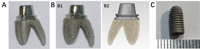
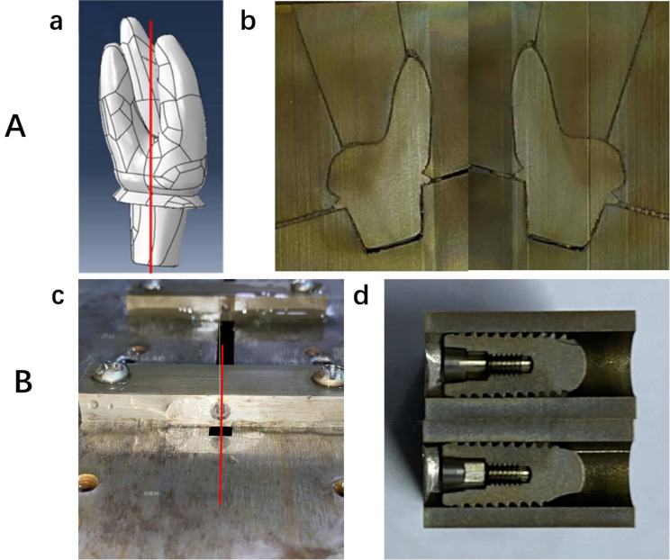
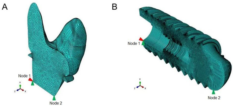
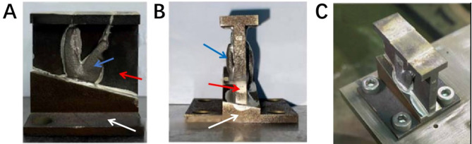
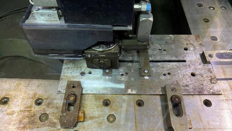
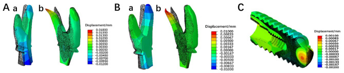
Methods: Three implant types (solid RAIs, mesh RAIs, and traditional threaded implants) were analyzed using contour cutting and finite element analysis to evaluate stress distribution and deformation trends after stress release.

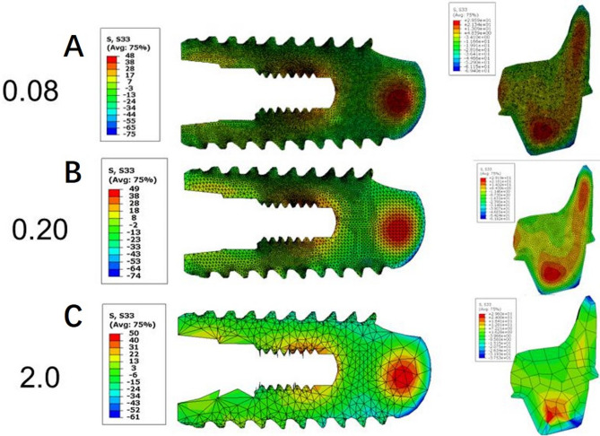
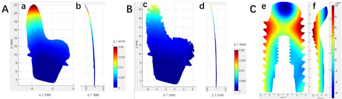
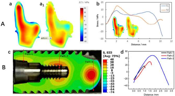
Results: RAIs exhibited lower tensile and compressive stresses than threaded implants (T1: 26 MPa vs. 48 MPa, T2: 18 MPa vs. 74 MPa), but showed greater displacement (T1: 0.02 mm, T2: 0.012 mm, T3: 0.0025 mm), mainly in the apical region.

Conclusions: RAIs offer advantages in stress distribution but require further optimization to address deformation. Future research should focus on improving material selection and manufacturing processes to enhance implant stability and long-term success.

Clinical trial number: Not applicable.

Keywords: 3D printing; Finite element analysis; Residual stress; Root-analogue implant.


Conflict of interest statement

Declarations. Ethics approval and consent to participate: Not applicable. Consent for publication: Not applicable. Competing interests: The authors declare no competing interests.

Figures

Fig. 1
Fig. 1
Implant samples: (A) RAI (Solid); (B1)RAI (Mesh); (B2) Corresponding drawings; (C) Threaded Implant
Fig. 2
Fig. 2
(A) RAI: (a) Contour cutting position(The model was developed based on scanned data from the RAI and used for finite element analysis.); (b) Cut surface after cutting. (B) Threaded implant: (a) Contour cutting position; (b) Cut surface after cutting
Fig. 3
Fig. 3
Finite element mesh models. the figure illustrates the finite element mesh representations of different implants used in the study to simulate residual stresses.(A) RAI; (B) Threaded Implant. Cinematic constraints were applied: Node 1 was fixed in the X and Y translational directions, and Node 2 was constrained along the Y-axis. Red are constrained in the x-direction, Green are constrained in the y-direction)
Fig. 4
Fig. 4
Convergence test on different mesh sizes for the threaded implant and RAI. Mesh sizes of 0.1 mm for the conventional implant and 0.3 mm for the RAI were selected for subsequent contour method calculations.Mesh sizes: (A) 0.08 mm; (B) 0.2 mm; (C) 2.0 mm
Fig. 5
Fig. 5
Utilize metal powder laser 3D printing to produce compensatory materials that match the sample’s outer contour, ensuring a stable EDM wire contact area and reducing cutting errors. Custom fixtures secure the sample on the EDM machine, maintaining consistent contact length and minimizing defects from size variations or wire entry/exit, ensuring high-quality measurements: (A)(B) Assembly display of samples, compensatory material, and fixed fixture; (C) Sample fixed on the cutting machine table before cutting. (Blue arrow: RAI; Red arrow: Compensatory material; White arrow: Fixed fixture.)
Fig. 6
Fig. 6
Assembled sample fixed on the cutting machine table: precisely assembled custom fixtures, sacrificial materials, and samples, securing them on the wire-cut EDM machine to maintain stable contact length, reduce cutting defects, and achieve high-quality measurement results
Fig. 7
Fig. 7
(A) T1 sample cut surface contour cloud diagram: (a) Z Perspective; (b) X Perspective; (B) T2 sample cut surface contour cloud diagram: (c) Z Perspective; (d) X Perspective; (C) T3 sample cut surface contour cloud diagram: (e) Z Perspective; (f) X Perspective
Fig. 8
Fig. 8
(A) RAIs: two-dimensional distribution of normal residual stress of the cut surface: (a) Sample T1; (a1) Sample T2; (b) Stress line distribution at the midpoint between the two samples, with paths indicated by the blue and orange arrows. (B) Threaded implant: (c) Two-dimensional distribution of normal residual stress of the cut surface for sample T3; (d) Comparison of stress extraction along different paths: Path-1 and Path-2 show that the stress changes from compressive stress at the surface to tensile stress at the center. Path 3 indicates that the stress at the center of the solid region at the top is tensile, while the surface on both sides exhibits compressive stress. (Colors represent stress magnitude: + indicates tensile stress, - indicates compressive stress.)
Fig. 9
Fig. 9
Overall deformation in the direction normal to the cut surface after cutting. The black dot matrix profile represents the position before cutting, while the colored solid model indicates the deformed position after cutting: (A) Sample T1: (a) Left side; (b) Right side. (Displacement magnified 200 times.) (B) Sample T2: (a) Left side; (b) Right side. (C) Sample T3 (Displacement magnified 400 times.)

References

    1. Liu M, Wang Y, Zhang S, Wei Q, Li X. Success factors of additive manufactured root analogue implants. Acs Biomater Sci Eng. 2022;8(2):360–78. - PubMed
    1. Lin C, Hu H, Zhu J, Wu Y, Rong Q, Tang Z. Influence of sagittal root positions on the stress distribution around custom-made root-analogue implants: a three-dimensional finite element analysis. BMC Oral Health. 2021;21(1):443. - PMC - PubMed
    1. Figliuzzi MM, Aiello D, Rengo C, Parentela L, Mangano C. 10-Year evaluation of the first root analogue implant on humans, made using a CT scan, CAD/CAM and dmls. Biomimetics (Basel). 2022;7(1):32. - PMC - PubMed
    1. Yu X, Feng B, Lan Y, Li J, Ye G, Li Q, Zhao F, Gu Y, You D, Zhu Y, Yu M, Wang H, Yang H. A 2-stage root analog implant with compact structure, uniform roughness, and high accuracy. J Dent Res. 2023;102(6):636–44. - PubMed
    1. Matsko A, Shaker N, Fernandes ACBCJ, Haimeur A, França R. Nanoscale chemical surface analyses of recycled powder for direct metal powder bed fusion Ti-6Al-4V root analog dental implant: an X-ray photoelectron spectroscopy study. Bioengineering (Basel). 2023;10(3):379. - PMC - PubMed

Publication types

Substances

LinkOut - more resources