. 2025 Jul;30(7):076002.
doi: 10.1117/1.JBO.30.7.076002. Epub 2025 Jul 3.

Flexible catheter optical coherence tomography of the porcine middle ear via the Eustachian tube using a 3D-printed reflective objective

Affiliations

Flexible catheter optical coherence tomography of the porcine middle ear via the Eustachian tube using a 3D-printed reflective objective

Clayton B Walker et al. J Biomed Opt. 2025 Jul.

Abstract

Significance: Cholesteatomas, benign tumors that grow in the middle ear, can lead to conductive hearing loss. If not completely removed during surgery, these tumors may regrow. Current imaging technologies struggle to detect residual tumors noninvasively due to limitations in contrast and resolution, often necessitating additional surgery for inspection. To address this, we developed a catheter endoscope capable of being inserted through the Eustachian tube, allowing detailed examination of the middle ear without surgery. Using two-photon polymerization (2PP) technology, we fabricated miniature, side-viewing reflective endoscope objectives. This approach enabled the rapid production of single-element objectives with highly repeatable optical properties, easily adaptable to specific imaging needs.

Aim: We aim to design, fabricate, and demonstrate a catheter endoscope for optical coherence tomography (OCT) endoscopy of the middle ear via the Eustachian tube.

Approach: Side-viewing, reflective lenses were designed in OpticStudio and 3D printed using 2PP followed by sputter coating with gold. Standard metrology techniques were used to verify and optimize the objective's shape. The optical performance of the catheter endoscopes was measured with a beam profiler. Finally, OCT imaging of the middle ear of a pig via the Eustachian tube was completed using the fully assembled catheter endoscope.

Results: Metrology showed the printed lenses conformed closely to the design. The catheter endoscope's FWHM spot size had a mean ± standard deviation of 25.3 ± 1.8 μ m with a measured working distance of 1.960 ± 0.057 mm . Volumetric OCT images of the middle ear, inner ear, and Eustachian tube were captured in a postmortem pig head using the catheter endoscope.

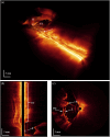
Conclusions: The 2PP approach is fast and highly repeatable for miniature reflective objective fabrication. OCT catheter endoscopy via the Eustachian tube enabled imaging of the middle ear, Eustachian tube, and surprisingly part of the inner ear.

Keywords: additive manufacturing; catheter endoscope; optical coherence tomography; two-photon polymerization.


Figures

Fig. 1
Fig. 1
Panels (a) and (b) are orthogonal 3D views, y to z and x to y, respectively, of the optical model in Zemax. All of the components of the catheter are modeled as optical elements. Slightly different outer diameters were used for the elements to make them more visible in the drawing. Panel (a) shows the y to z view of the optical design where the output from the fiber is coming out of the page, RL indicates the reflective lens, ST indicates the shrink tubing that seals the air gap between the fiber output and the reflective lens, W indicates the water inside the catheter which is also highlighted for clarity, and CT indicates the catheter tubing. Panel (b) provides an x to y view showing a better angle of the mirror surface where all surfaces are labeled like panel (a). Panel (c) shows the enface view of the slightly elliptical beam in the POP window. It also indicates a Rayleigh range of 1.08 mm, a beam FWHMx of 25.5  μm, and a FWHMy of 24.2  μm below the plot.
Fig. 2
Fig. 2
Panel (a) shows the side view of the probe. Panel (b) shows the front view of the probe. Panel (c) shows the STL of the probe in NanoprintX software. Panel (d) shows the probe fabricated in an array (e) closer look at the fabricated probe. Panel (f) is a high-resolution photo of the probe after coating.
Fig. 3
Fig. 3
Results from a confocal metrology system used to measure the biconic surface of the reflective lens. Panel (a) shows the heat map of the topography of the reflective lens. Panel (b) shows the cross-sectional profile taken along the y-axis (top) and x-axis (bottom) through the center of the reflective lens. From these profiles, the radius of curvature along each axis was taken to compare with those expected in the design.
Fig. 4
Fig. 4
Key steps in catheter fabrication in order: (a) cleaved fiber inserted into probe, (b) glue the fiber and probe together, (c) add torque coil (TC), torque adapter (TA), fiber connector (FC), and protective steel tubing, (d) seal the airgap between the cleaved fiber and probe mirror with FEP shrink tubing (ST), and (e) insert finished catheter endoscope into catheter.
Fig. 5
Fig. 5
(a) Diagram of the OCT system used for imaging experiments. Panel (b) shows a diagram of the spiral pullback volumetric imaging technique. Here, the solid red lines represent the beam exiting the catheter endoscope, and the dotted red line shows an exaggerated path the beam would be scanned as it is pulled along the length of the housing and rotated. The pullback speed was chosen to provide a 12.5  μm spacing between each full rotation.
Fig. 6
Fig. 6
(a) Catheter endoscope being inserted through the Eustachian tube entrance as indicated by the yellow arrow. (b) Green light can be seen from the middle ear space—indicating the catheter endoscope reached the middle ear. The blue arrow points out the resected ear canal for reference. The rectangle shown in panel (b) shows the region that the magnified image in panel (c) is highlighting. In panel (c), the handle of the malleus is indicated by the light blue arrow and can be clearly seen through the tympanic membrane. (d) The catheter endoscope is indicated by the yellow arrow. The white dotted line was aligned with the visible parts of the catheter endoscope and shows that it is oriented near the handle of the malleus, which is indicated by the light blue arrow.
Fig. 7
Fig. 7
All the images here are orthogonal to each other. Panel (a) is a snapshot of the video feed from the surgical microscope that shows middle ear structures and the catheter endoscope orientation as the white dotted line. EC is the ear canal, FN is the facial nerve, CT is the chorda tympani, MH is the malleus head, H is the malleus handle, and TM is the tympanic membrane—which covers most of the right-hand side of the image. Panel (b) is the OCT B-scan taken along the green dashed line in the x to z plane where M is the malleus, I is the incus, CE is a portion of the catheter endoscope, and P is the cochlear promontory. Panel (c) is the OCT B-scan taken along the blue dashed line in the y to z plane.
Fig. 8
Fig. 8
(a) Volumetric OCT image of the middle ear space taken with the catheter endoscope. Here, H is the handle of the malleus, U is the umbo of the tympanic membrane, CT is the chorda tympani, and ET is the Eustachian tube. The arrow indicates part of the catheter—seen here as a perfect cylinder. Panel (b) shows many layers of cartilage and fatty deposits along a cross-section of the Eustachian tube along with the umbo in the middle ear. Panel (c) is an orthogonal cross-section to panel (b) where the handle of the malleus (H) is seen with a lot of connective tissue (L), likely ligaments, attaching to it, the tympanic membrane (TM), and the attic wall of the middle ear.
Fig. 9
Fig. 9
Cross-sectional OCT images of the cochlea scala (S) in the volumetric images collected with the catheter endoscope. Panels (a) and (c) are longitudinal (pullback) cross-sections that show the scala within the cochlea and the subsurface layers of the Eustachian tube. Panel (b) shows the transverse (rotational) cross section showing the incudomalleolar joint where the incus (I) and malleus (M) meet with the tympanic membrane (TM) above the ossicles. These frames are related cross-sectional images where the color of the frame around each image matches the color of the scout lines in the other two frames. These scout lines show where the frame’s cross-sectional image comes from.

References

    1. Djalilian H. R., et al. , “Optical coherence tomography of cholesteatoma,” Otol. Neurotol. 31(6), 932–935 (2010). 10.1097/MAO.0b013e3181e711b8 - DOI - PMC - PubMed
    1. Kim W., et al. , “Optical coherence tomography otoscope for imaging of tympanic membrane and middle ear pathology,” J. Biomed. Opt. 29(8), 086005 (2024). 10.1117/1.JBO.29.8.086005 - DOI - PMC - PubMed
    1. Tearney G. J., et al. , “Three-dimensional coronary artery microscopy by intracoronary optical frequency domain imaging,” JACC Cardiovasc. Imaging 1(6), 752–761 (2008). 10.1016/j.jcmg.2008.06.007 - DOI - PMC - PubMed
    1. Adler D. C., et al. , “Three-dimensional endomicroscopy of the human colon using optical coherence tomography,” Opt. Express 17(2), 784–796 (2009). 10.1364/OE.17.000784 - DOI - PMC - PubMed
    1. Tsai T.-H., et al. , “Ultrahigh speed endoscopic optical coherence tomography for gastroenterology,” Biomed. Opt. Express 5(12), 4387–4404 (2014). 10.1364/BOE.5.004387 - DOI - PMC - PubMed

Publication types