Clinical Trial
. 2025 Jul;53(5):529-541.
doi: 10.1111/ceo.14502. Epub 2025 Jan 31.

Second-Generation (44-Channel) Suprachoroidal Retinal Prosthesis: Surgical Stability and Safety During a 2-Year Clinical Trial

Collaborators, Affiliations
Clinical Trial

Second-Generation (44-Channel) Suprachoroidal Retinal Prosthesis: Surgical Stability and Safety During a 2-Year Clinical Trial

Penelope J Allen et al. Clin Exp Ophthalmol. 2025 Jul.

Abstract

Background: To assess the safety and stability profile of the suprachoroidal retinal prosthesis (ScRP) in participants with retinitis pigmentosa (RP) for 2 years from implantation.

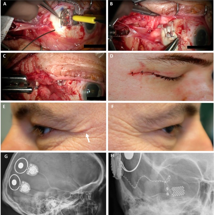
Methods: Four participants, with advanced RP and bare-light perception vision were enrolled in a prospective, single arm unmasked interventional clinical trial and unilaterally implanted with a 44-channel ScRP (NCT03406416). Electrical stimulation commenced in the psychophysics laboratory prior to use in local environments. Outcome measures included serious adverse events, adverse events, implant stability and implant functionality to assess the safety and stability profile over 2.0-2.7 years.

Results: Surgical procedures took 204-260 min and were uncomplicated. Postoperative recovery was uneventful. Imaging confirmed the device position under the macula and the absence of retinal trauma. There were no serious adverse events and the adverse events that occurred were mild. All electrodes were functional at surgery completion, and only 3% electrodes lost functionality by study end. There was minor array movement (translational and rotational) within the first 10-15 weeks only. The electrode to retina distance increased as expected with fibrous capsule development, but plateaued in three of four participants within 12 months. Retinal and choroidal thicknesses were consistent with the underlying retinal dystrophic disease.

Conclusions: The ScRP can be safely implanted in the suprachoroidal space and has minimal long-term impacts on the eye, with no SAEs and only slight array movement seen over 2.0-2.7 years. Hence, the findings indicate approach feasibility and further multicentre studies are warranted.

Keywords: adverse events; bionic eye; retinitis pigmentosa; suprachoroidal retinal prosthesis; surgical safety.


Conflict of interest statement

P.J.A., D.A.X.N., J.V., C.E.W. and M.A.P. hold patents in relation to this work. P.J.A., M.K., E.K.B., S.A.T., J.K., D.A.X.N., C.D.L., M.A.P. and C.J.A. received financial support for the work from Bionic Vision Technologies. M.K., E.K.B., M.A.P. and C.J.A. received travel funding from Bionic Vision Technologies to present this work at an international conference in 2019. J.Y., R.J.B. and M.B.M. declare no conflicts of interest.

Figures

FIGURE 1
FIGURE 1
ScRP components. (A) Implantable device components, consisting of two magnetic coil receiver‐stimulators, each connecting to the electrode array via a cable with single strand helical wires from each electrode. (B) The electrode array, consisting of seven rows of 1 mm diameter platinum electrodes, with two larger return electrodes (2 mm diameter), imbedded in a rectangular silicone substrate, dimensions 19 ± 0.1 × 8 ± 0.1 × 0.6 mm (length, width, height). (C) External components of device for a right eye implant consisting of a small camera on the side of a pair of custom spectacles with a wired connection to the portable vision processing unit. Reprinted photographs under CC‐ND licences from Translational Vision Science and Technology, Vol 10 (10), Petoe et al., a second‐generation (44‐channel) suprachoroidal retinal prosthesis: Interim clinical trial results, p12, copyright (2021), and Translational Vision Science and Technology, Vol 11 (9), Abbott et al., inter‐observer agreement of electrode to retina distance measurement in a second‐generation (44‐channel) suprachoroidal retinal prosthesis, p4, copyright (2022).
FIGURE 2
FIGURE 2
Surgical implantation of suprachoroidal device steps. (A) Lateral canthotomy is performed. (B) Dissection from wound behind pinna with trocar to enable passage of device. (C) Drilling of orbitotomy for cable stabilisation. (D) Isolation of lateral rectus muscle to temporarily disinsert it. (E) Creation of the scleral incision. (F) Dissection of suprachoroidal space. (G) Exploration of suprachoroidal space with lens glide. (H) Insertion of the electrode array into the suprachoroidal space beneath the macula. (I) Creation of L‐shaped extension of wound to allow egress of the lead. (J) The Dacron patch is sutured to the globe and the cable grommet is placed within the orbitotomy. (K) Lateral rectus is reattached, and the periosteum is closed over the cable. (L) All wounds are closed.
FIGURE 3
FIGURE 3
Photographs of key stages of the intraocular component of surgery and post‐surgical outcomes (S1) and X‐rays demonstrating the position of the implantable device components at 20 months post‐implantation (S4). (A) Electrode array being inserted into suprachoroidal space. (B) Suturing the Dacron patch. (C) Lateral rectus muscle reattached over the scleral wound. (D) Skin closure of lateral canthotomy. (E and F) Two‐year post‐implantation photographs demonstrating minimal scarring from the lateral canthotomy (arrow) in the implanted eye (E) compared to the fellow non‐implanted eye (F). (G) Lateral X‐ray of right side of skull showing the two receiver‐stimulators positioned on the temporal cranial bone. Each receiver‐stimulator is connected to the electrode array by the helical cable. (H) Anteroposterior X‐ray of right side of skull, with the eye in primary gaze, showing the suprachoroidal electrode array position and connection of the cable to the receiver‐stimulators.
FIGURE 4
FIGURE 4
Occurrence of reported adverse events (AEs), from 30 days post‐surgical implantation to study endpoint. This graph includes reported AEs related to device use, study procedures and study tasks. AE events included are those that were classified as possibly, probably and definitely related to the device presence or use.
FIGURE 5
FIGURE 5
Choroidal effusion event in S1 noted at 2.5 months post‐implantation. (A–D) Colour fundus photos, near infrared images, the focus setting in Dioptres on the Heidelberg Spectralis and the OCT B‐scan image through the superior row of the electrode array, showing elevation of the array and overlying retina and the subsequent recovery over 3‐months ((A) at pre‐event, (B) retinal elevation during event, (C) 1‐month after event onset, (D) 3‐months after event onset). (E) B‐scan ultrasound positioned through optic nerve. (F) B‐scan ultrasound positioned temporal to optic nerve. Shadows posterior to the array are cast by the platinum electrodes. There was no sign of retinal, subretinal or suprachoroidal haemorrhage (no attenuation of ultrasound signal), hence the event was diagnosed as a choroidal effusion that resolved without treatment. Arrows indicate the position of electrode array within the suprachoroidal space.
FIGURE 6
FIGURE 6
Colour fundus photos and near infrared images (montage stitched in Heyex software) showing the electrode array position for each participant over time. The foveal position is shown with a blue cross. All participants recovered well post‐surgery and the device remained stable within the suprachoroidal space for over 2 years. In S2 and S3, there were subtle subretinal haemorrhages that had resolved in 2 weeks. S1 had greater pigmentation of the ocular fundus due to racial variation that did not allow for viewing of the electrode array on colour fundus photo, however the array is visible on near infrared.
FIGURE 7
FIGURE 7
Rotational and translational movement of the electrode array in each participant relative to baseline. The translational movement was calculated for horizontal (Hor.) and vertical (Ver.) directions. The array is stable over time across participants after an initial settling period of 10–15 weeks.
FIGURE 8
FIGURE 8
Representative OCT B‐scans from S1 showing the choroidal thickness remains consistent over 2 years above passive (A and B) and active (C and D) electrodes as well as in a comparative position (macula) of the fellow eye (E and F). The positions of the measurements are shown relative to the electrode array schematic (G). Orange box/circles indicates passive (A18) and active (B3) electrodes. Blue cross indicates the position of fovea relative to positions that choroid was measured (orange circles for implanted eye, grey circle for fellow eye). Blue line indicates choroidal thickness; passive baseline = 193 μm, passive 2 years = 195 μm; active baseline = 141 μm, active 2 years = 134 μm; fellow baseline = 212 μm, fellow 2 years = 204 μm. Scale bar = 200 μm.

References

    1. Ramirez K. A., Drew‐Bear L. E., Vega‐Garces M., Betancourt‐Belandria H., and Arevalo J. F., “An Update on Visual Prosthesis,” International Journal of Retina and Vitreous 9, no. 1 (2023): 1–16. - PMC - PubMed
    1. Ayton L. N., Barnes N., Dagnelie G., et al., “An Update on Retinal Prostheses,” Clinical Neurophysiology 131, no. 6 (2020): 1383–1398. - PMC - PubMed
    1. Allen P. J., “Retinal Prostheses: Where to From Here?,” Clinical & Experimental Ophthalmology 49, no. 5 (2021): 418–429. - PubMed
    1. Luo Y. H.‐L. and Da Cruz L., “The Argus® II Retinal Prosthesis System,” Progress in Retinal and Eye Research 50 (2016): 89–107. - PubMed
    1. Hornig R., Dapper M., Le Joliff E., et al., “Pixium Vision: First Clinical Results and Innovative Developments,” in Artificial Vision: A Clinical Guide (Cham, Switzerland: Springer, 2017).

Publication types

LinkOut - more resources