

A Review on UAS Trajectory Estimation Using Decentralized Multi-Sensor Systems Based on Robotic Total Stations
- PMID: 40648097
- PMCID: PMC12251799
- DOI: 10.3390/s25133838
A Review on UAS Trajectory Estimation Using Decentralized Multi-Sensor Systems Based on Robotic Total Stations
Abstract
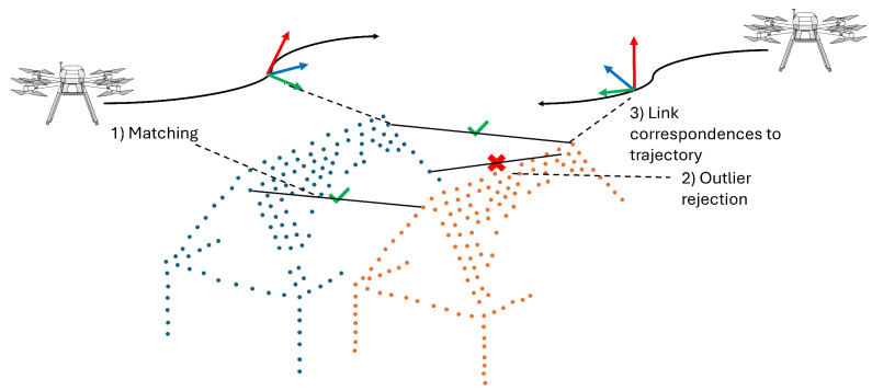
In our contribution, we conduct a thematic literature review on trajectory estimation using a decentralized multi-sensor system based on robotic total stations (RTS) with a focus on unmanned aerial system (UAS) platforms. While RTS are commonly used for trajectory estimation in areas where GNSS is not sufficiently accurate or is unavailable, they are rarely used for UAS trajectory estimation. Extending the RTS with integrated camera images allows for UAS pose estimation (position and orientation). We review existing research on the entire RTS measurement processes, including time synchronization, atmospheric refraction, prism interaction, and RTS-based image evaluation. Additionally, we focus on integrated trajectory estimation using UAS onboard measurements such as IMU and laser scanning data. Although many existing articles address individual steps of the decentralized multi-sensor system, we demonstrate that a combination of existing works related to UAS trajectory estimation and RTS calibration is needed to allow for trajectory estimation at sub-cm and sub-0.01 gon accuracies, and we identify the challenges that must be addressed. Investigations into the use of RTS for kinematic tasks must be extended to realistic distances (approx. 300-500 m) and speeds (>2.5 m s-1). In particular, image acquisition with the integrated camera must be extended by a time synchronization approach. As to the estimation of UAS orientation based on RTS camera images, the results of initial simulation studies must be validated by field tests, and existing approaches for integrated trajectory estimation must be adapted to optimally integrate RTS data.
Keywords: 6-DoF trajectory estimation; UAV; image-assisted total station; sensor synchronization.
Conflict of interest statement
Author David Monetti is part of the company Skyability GmbH. The remaining authors declare that the research was conducted in the absence of any commercial or financial relationships that could be construed as a potential conflict of interest.
Figures


References
-
- Dreier A., Janßen J., Kuhlmann H., Klingbeil L. Quality Analysis of Direct Georeferencing in Aspects of Absolute Accuracy and Precision for a UAV-Based Laser Scanning System. Remote Sens. 2021;13:3564. doi: 10.3390/rs13183564. - DOI
-
- Skaloud J., Lichti D. Rigorous approach to bore-sight self-calibration in airborne laser scanning. ISPRS J. Photogramm. Remote Sens. 2006;61:47–59. doi: 10.1016/j.isprsjprs.2006.07.003. - DOI
-
- Pöppl F., Neuner H., Mandlburger G., Pfeifer N. Integrated trajectory estimation for 3D kinematic mapping with GNSS, INS and imaging sensors: A framework and review. ISPRS J. Photogramm. Remote Sens. 2023;196:287–305. doi: 10.1016/j.isprsjprs.2022.12.022. - DOI
-
- Subirana J.S., Zornoza J.J., Hernández-Pajares M. Time References in GNSS. 2011. [(accessed on 15 May 2025)]. Available online: https://gssc.esa.int/navipedia/index.php/Time_References_in_GNSS.
-
- Thalmann T., Neuner H. Temporal calibration and synchronization of robotic total stations for kinematic multi-sensor-systems. J. Appl. Geod. 2021;15:13–30. doi: 10.1515/jag-2019-0070. - DOI
Publication types
Grants and funding
LinkOut - more resources
Full Text Sources
Research Materials
