. 2025 Jul 22;122(29):e2500526122.
doi: 10.1073/pnas.2500526122. Epub 2025 Jul 15.

Electrokinetic propulsion for electronically integrated microscopic robots

Affiliations

Electrokinetic propulsion for electronically integrated microscopic robots

Lucas C Hanson et al. Proc Natl Acad Sci U S A. .

Abstract

Semiconductor microelectronics are emerging as a powerful tool for building smart, autonomous sub-millimeter robots. Yet a number of existing microrobot platforms, despite significant advantages in speed, robustness, power consumption, or ease of fabrication, have no clear path toward electronics integration, limiting their potential for intelligence. Here, we show how to upgrade a class of self-propelled particles into electronically integrated microrobots, reaping the best of both platforms in a single design. Inspired by electrokinetic micromotors, these robots generate electric fields in a surrounding fluid, and by extension propulsive electrokinetic flows. The underlying physics is captured by a model in which robot speed is proportional to applied current, making design and control straightforward. As proof, we build basic robots at the 100-micron scale that use rudimentary, on-board photovoltaic circuits and a closed-loop optical control scheme to navigate waypoints and move in coordinated swarms at speeds of up to one body length per second. Broadly, the unification of micromotor propulsion with on-robot electronics invites future work to realize robust, fast, easy to manufacture, electronically programmable microrobots that remain operationally viable for months to years.

Keywords: electrokinetic propulsion; micromotors; microrobots.


Conflict of interest statement

Competing interests statement:The authors declare no competing interest.

Figures
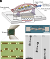
Fig. 1.
Fig. 1.
Electrokinetic propulsion for microrobots. (A) Schematic of the electrokinetic mechanism. Mobile ions in the electrical double layer migrate in the presence of an electric field, E, and generate fluid flows around the device that cause locomotion. (B) Optical image of a silicon chip with hundreds of robots on it, with various shapes and PV numbers. Beneath it, a micrograph of various robot designs on chip, fabricated massively in parallel with 400 devices per 1.5 cm square chip (Scale bar, 500 μm.) (C) Micrograph of a 4 PV design with Ti/Pt electrodes at both ends of the device’s SiO2 body (Scale bar, 100 μm.) (D) Montage of a device moving under global microscope illumination in solution (Scale bar, 200 μm.)
Fig. 2.
Fig. 2.
Characterization of propulsion mechanism. (A) Speed vs. electric field behavior for a variety of chemical environments scaled by the robot’s effective mobility Δβ (that is V=ΔβE; see Materials and Methods). The black line is unity. The Upper Inset depicts speed vs. electric field data for a robot in 5 mM hydrogen peroxide, where conductivity and applied current are independently varied. The Lower Inset details the variation of the effective mobility for different solution compositions. (B and C) Data for the angle of attack and gap height vs. speed, respectively. The black curves are the results of numerical fitting of the data to our fluid model (SI Appendix, section C). The Insets show micrographs of a moving robot viewed from the side and front used to produce the data (Scale bars, 100 μm, Materials and Methods.) Note that the same robot and chemical environment (5 mM peroxide) were used to measure all data in panels (B and C).
Fig. 3.
Fig. 3.
Control and kinematics of a two motor robot. (A) A closed-loop optical system for automated control over robots. After each frame capture, a computer performs object detection and generates a new optical pattern to control robots. (B) A diagram depicting the variables involved in our control laws. (C) As expected for differential drive kinematics, the curvature κ nondimensionalized using the robot width δ is proportional to the normalized difference between motor velocities η when accounting for optical effects α (see SI Appendix for discussion on stray light correction, SI Appendix, section D). The black line has slope = −1. (D) Implementation of a differential drive controller, where power to each motor is simultaneously adjusted in order to place the robot at specific locations. See Movie S4. (E) Path trace of a controller that adjusts only the most misaligned motor to pilot the robot around a lemniscate. See Movie S5.
Fig. 4.
Fig. 4.
Addressability and swarming behavior enabled by circuits. (A and B) The control program can be given a list of target positions in order to guide each robot to its nearest waypoint. (C) Robots can be assigned individual lists of waypoints in order to trace out separate paths in unison. (D) Waypoints can also be dynamic and change at each timestep. Shown in blue, “follower” robots are assigned the location of another robot in the system as a waypoint. This rule results in chain-like structures following the “leader,” shown in red.

References

    1. X. Wu et al. , “A 0.04MM316NW wireless and batteryless sensor system with integrated cortex-M0+ processor and optical communication for cellular temperature measurement” in 2018 IEEE Symposium on VLSI Circuits, K. Chang, K. Takeuchi, Eds. (IEEE, 2018), pp. 191–192.
    1. K. Blutman et al. , A low-power microcontroller in a 40-nm CMOS using charge recycling. IEEE J. Solid State Circuits 52, 950–960 (2017).
    1. A. T. Do, S. M. A. Zeinolabedin, D. Jeon, D. Sylvester, T. T. H. Kim, An area-efficient 128-channel spike sorting processor for real-time neural recording with 0.175 μW/channel in 65-nm CMOS. IEEE Trans. Very Large Scale Integr. Syst. 27, 126–137 (2019).
    1. S. Lee et al. , A 250 um × 57 um Microscale Opto-electronically Transduced Electrodes (MOTEs) for neural recording. IEEE Trans. Biomed. Circuits Syst. 12, 1256–1266 (2018). - PMC - PubMed
    1. G. Atzeni et al. , “A 260×274 um2 572 nW neural recording micromote using near-infrared power transfer and an RF data uplink” in 2022 IEEE Symposium on VLSI Technology and Circuits (VLSI Technology and Circuits), G. Jurczak, B. Nikolić, Eds. (IEEE, 2022), pp. 64–65.

LinkOut - more resources