

Analysis of electromagnetic coupling between two compartments of an aircraft cabin through an aperture
- PMID: 40665005
- PMCID: PMC12264279
- DOI: 10.1038/s41598-025-11249-7
Analysis of electromagnetic coupling between two compartments of an aircraft cabin through an aperture
Abstract
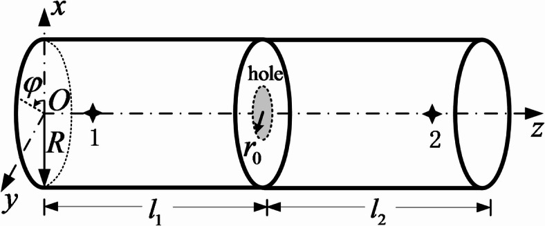
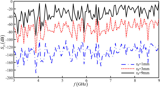
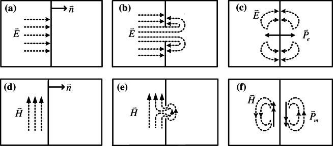
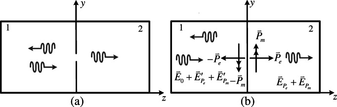
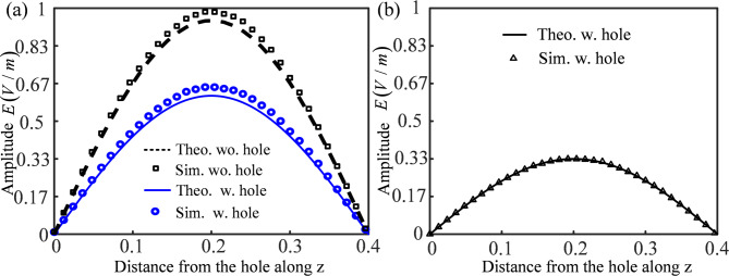
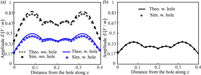
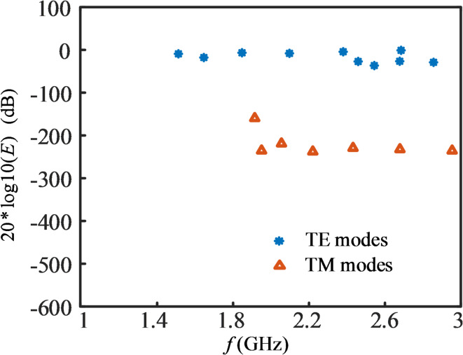
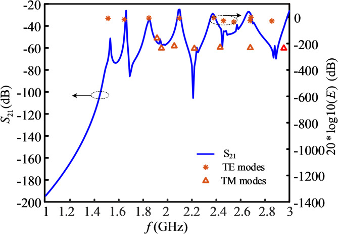
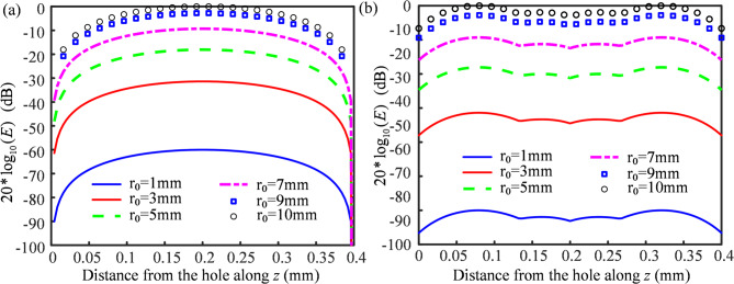
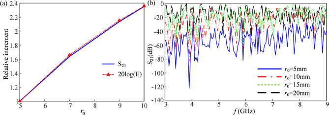
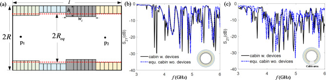
Wireless communication technology has emerged as a significant development direction in the aerospace domain. Different compartments in an aircraft are typically physically separated by metal partitions, which makes electromagnetic (EM) coupling unattainable. In this study, we propose using a small aperture on the partition to establish an EM connection instead of cables. The effect of the aperture on the partition can be represented by an electric dipole and a magnetic dipole, which are mutually orthogonal and parallel to the partition, respectively. Analytical expressions for the electromagnetic field within the two compartments are derived, incorporating both spatial and frequency dispersion. The theoretical analysis indicates that the EM filed exhibits typical multi-resonant characteristics. Furthermore, simulation analysis is performed using Ansys HFSS, the electric field distribution in two compartments for both single-mode or multi-mode are extracted. A remarkable agreement between the simulation data and the theoretical predictions is observed. In addition, the relationship between the electromagnetic (EM) field and transmission curve between a radiator and receiver in the compartments is discussed, a positive correlation has been demonstrated. The findings presented in this paper establishes a solid theoretical basis for enabling wireless communication between two compartments within an aircraft cabin.
© 2025. The Author(s).
Conflict of interest statement
Declarations. Competing interests: The authors declare no competing interests.
Figures
Similar articles
-
Short-Term Memory Impairment.2024 Jun 8. In: StatPearls [Internet]. Treasure Island (FL): StatPearls Publishing; 2025 Jan–. 2024 Jun 8. In: StatPearls [Internet]. Treasure Island (FL): StatPearls Publishing; 2025 Jan–. PMID: 31424720 Free Books & Documents.
-
Comparison of Two Modern Survival Prediction Tools, SORG-MLA and METSSS, in Patients With Symptomatic Long-bone Metastases Who Underwent Local Treatment With Surgery Followed by Radiotherapy and With Radiotherapy Alone.Clin Orthop Relat Res. 2024 Dec 1;482(12):2193-2208. doi: 10.1097/CORR.0000000000003185. Epub 2024 Jul 23. Clin Orthop Relat Res. 2024. PMID: 39051924
-
[Volume and health outcomes: evidence from systematic reviews and from evaluation of Italian hospital data].Epidemiol Prev. 2013 Mar-Jun;37(2-3 Suppl 2):1-100. Epidemiol Prev. 2013. PMID: 23851286 Italian.
-
A Novel Design of a Portable Birdcage via Meander Line Antenna (MLA) to Lower Beta Amyloid (Aβ) in Alzheimer's Disease.IEEE J Transl Eng Health Med. 2025 Apr 10;13:158-173. doi: 10.1109/JTEHM.2025.3559693. eCollection 2025. IEEE J Transl Eng Health Med. 2025. PMID: 40657533 Free PMC article.
-
The Black Book of Psychotropic Dosing and Monitoring.Psychopharmacol Bull. 2024 Jul 8;54(3):8-59. Psychopharmacol Bull. 2024. PMID: 38993656 Free PMC article. Review.
References
-
- Schuster, T. Networking concepts comparison for avionics architecture. In IEEE/AIAA 27th Digit. Avionics Syst. Conf. (ed Verma, D.) 10.1109/dasc.2008.4702761 (2008).
-
- Reji, P., Natarajan, K. & Shobha, K. R. Performance evaluation of wireless protocols for avionics wireless network. J. Aerosp. Inform. Syst.. 10.2514/1.i010752 (2019).
-
- Dinh-Khanh Dang, Mifdaoui, A. & Gayraud, T. Fly-by-wireless for next generation aircraft: challenges and potential solutions. In 2012 IFIP Wireless Days. 10.1109/wd.2012.6402820 (2012).
-
- Samano-Robles, R., Tovar, E., Cintra, J. & Rocha, A. Wireless avionics intra-communications: Current trends and design issues. In 2016 Eleventh International Conference on Digital Information Management (ICDIM). 10.1109/icdim.2016.7829798 (2016).
-
- Akram, R. et al. Security and performance comparison of different secure channel protocols for avionics wireless networks. In 2016 IEEE/AIAA 35th Digit. Avionics Syst. Conf. (DASC). 10.1109/dasc.2016.7777966 (2016).
Grants and funding
LinkOut - more resources
Full Text Sources
Miscellaneous
