. 2025 Jul-Aug;39(4):e70175.
doi: 10.1111/jvim.70175.

Orthodromic Atrioventricular Reentry Bradycardia and Tachycardia Caused by an Accessory Pathway in Horses

Affiliations

Orthodromic Atrioventricular Reentry Bradycardia and Tachycardia Caused by an Accessory Pathway in Horses

Eva Buschmann et al. J Vet Intern Med. 2025 Jul-Aug.

Abstract

Background: Accessory pathways (APs) are muscular bundles directly connecting the atria and ventricles, bypassing the atrioventricular (AV) node-His-Purkinje system. Anterograde conduction along the AP results in ventricular preexcitation. A retrograde conducting AP allows ventriculo-atrial (VA) conduction, creating a reentry circuit that mediates orthodromic atrioventricular reentry tachycardia (OAVRT). This condition is well described in humans and small animals, but has not been reported previously in horses.

Objectives: Describe clinical and electrocardiographic findings of horses with retrograde AP conduction and reporte mapping and radiofrequency ablation results in one horse.

Animals: Six horses with retrograde AP conduction.

Methods: Records from six horses with retrograde AP conduction were reviewed.

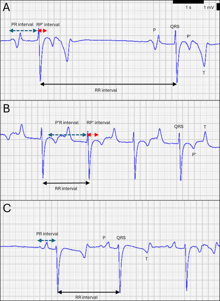
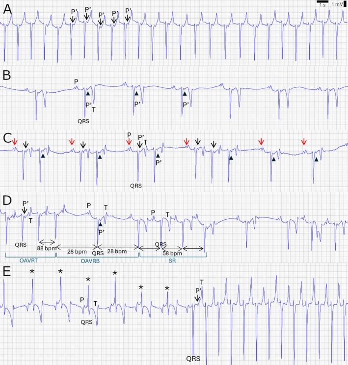
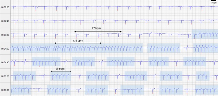
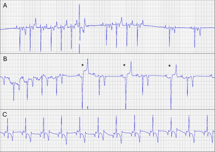
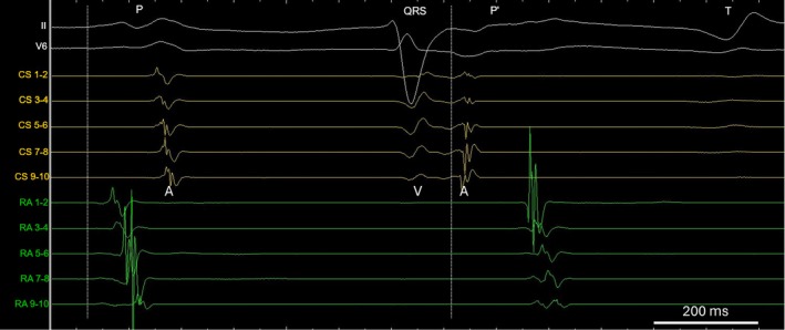
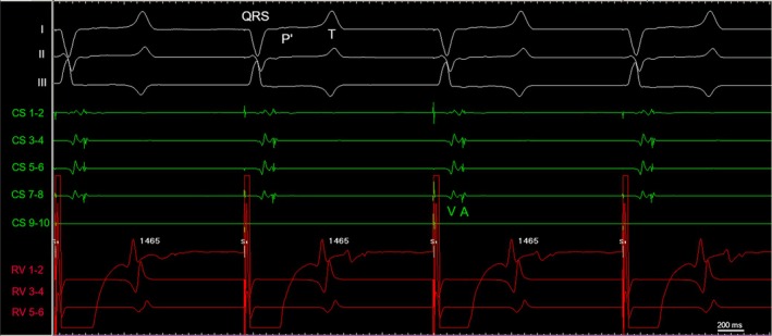
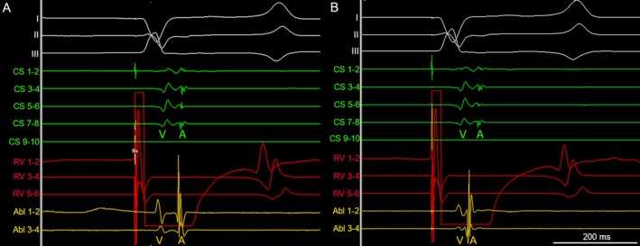
Results: Resting ECGs showed P' waves in the ST segment with fixed coupling intervals to the preceding QRS complexes. In five of six horses, P' waves were conducted back to the ventricles along the AV node, resulting in OAVRT. All horses had episodes where P' waves were blocked at the AV node, which resulted in orthodromic atrioventricular reentry bradycardia (OAVRB). In one horse, the AP conducted bidirectionally resulting in ventricular preexcitation. An electrophysiological study in one horse identified a left-atrial AP insertion by the shortest VA interval. Radiofrequency ablation using an impedance-based mapping system could not eliminate the AP.

Conclusions: Retrograde conducting APs in horses caused OAVRT and OAVRB. APs in horses behaved differently compared to those in humans and dogs. Further research is necessary to elucidate AP behavior, evaluate risk and effect on performance, and assess treatment by ablation.

Keywords: arrhythmias; bypass tract; electrophysiology; equine cardiology.


Conflict of interest statement

The authors declare no conflicts of interest.

Figures

FIGURE 1
FIGURE 1
Measurements performed during orthodromic atrioventricular reentry bradycardia (A), orthodromic atrioventricular reentry tachycardia (B) and sinus rhythm (C) are shown.
FIGURE 2
FIGURE 2
Resting electrocardiogram (A–D) are recorded in Case 5 using the Delta configuration [19], ECG (E) is recorded in Case 6 using the Dubois lead system. (A) ECG during orthodromic atrioventricular reentry tachycardia (OAVRT) at a heart rate of 90 beats per minute (bpm). A reentry circuit is formed by the atrioventricular (AV) node and accessory pathway. The ventricles are depolarized normally (orthodromic) along the AV node, leading to QRS complexes with normal morphology and duration. After ventricular activation, the impulse is conducted back to the atria along the accessory pathway (retrograde conduction). Retrograde conducted P′ waves (black arrows) are visible in the ST segment, have a short and fixed coupling interval with the preceding QRS complex, and conduct via the AV node back to the ventricles. (B) ECG during orthodromic atrioventricular reentry bradycardia (OAVRB) at a heart rate of 28 beats per minute (bpm). Retrograde conducted P′ waves in the ST segment (black arrowheads) are blocked at the level of the AV node. These P′ waves affect sinus node discharge which slows down the heart rate. (C) Irregular rhythm caused by normal sinus depolarizations (P waves: red arrows) that conduct to the ventricles, with retrograde P′ waves (black arrows) that conduct back to the ventricles and retrograde P′ waves (black arrowheads) that do not conduct back to the ventricles because they are blocked at the AV node. (D) On this trace, sinus rhythm (SR) and conduction along the accessory pathway are intermittently present. In the first four complexes, ventricular impulses are conducted to the atria via the accessory pathway and immediately conducted back to the ventricles (black arrow), resulting in OAVRT at a rate of 88 bpm. In the next two complexes, retrograde P′ waves are blocked at the AV node (black arrowhead), causing a relative bradycardia of 28 bpm, which is slower than during SR. The next three complexes are normal SR, without retrograde accessory pathway conduction. During normal sinus rhythm, a heart rate of 58 bpm is present. The relatively high sinus rate might be a compensatory mechanism due to reduced cardiac output or blood pressure during OAVRB. (E) Anterograde conduction along the accessory pathway was present in case 6 and resulted in ventricular preexcitation. The typical ECG characteristics are present in the complexes marked with an asterisk: a shortened PR interval and segment, abnormal QRS morphology and duration with a slurred upstroke of the QRS complex (delta wave). The degree of ventricular preexcitation gradually decreases and changes into orthodromic atrioventricular reentry tachycardia due to retrograde accessory pathway conduction.
FIGURE 3
FIGURE 3
Extract from a 24‐h ECG, lead II is shown over a time period of 4 min, at a paper speed of 10 mm/s and gain of 2.5 mm/mV. Retrograde conduction along the accessory pathway is present and results in orthodromic atrioventricular reentry bradycardia or tachycardia. Episodes of relative bradycardia and tachycardia are alternated. Episodes of tachycardia are marked by the blue boxes. Note the sudden onset and offset of tachycardia. Bpm: beats per minute.
FIGURE 4
FIGURE 4
Lead II of the resting electrocardiogram showing QRS complexes with an abnormal QRS morphology recorded in Case 1 (A), Case 5 (B), and Case 6 (C). (A) A QRS complex with abnormal QRS morphology occurs during orthodromic atrioventricular reentry tachycardia and was preceded by the retrograde conducting P′ wave with a shortened P′R interval. No delta wave could be detected. The abnormal QRS complex terminates the tachycardia episode. It is therefore likely that this is a ventricular premature complex. (B) Three abnormal QRS complexes, marked by an asterisk, were preceded by a P wave. The PR intervals were 352, 360, and 436 ms and no delta wave could be identified. Therefore, the complexes were thought to be ventricular premature complexes. (C) Abnormal QRS complexes, associated with a preceding P wave, a short PR interval and PR segment, and a delta wave (slurred upstroke of the QRS complex) indicated ventricular preexcitation due to anterograde conduction along the accessory pathway.
FIGURE 5
FIGURE 5
Surface 12‐lead ECG lead II and V6 (top white traces), five bipolar electrograms recorded within the coronary sinus (yellow traces) and five bipolar electrograms recorded in the right atrium at the intervenous tubercle (green traces) during a normal (orthodromic) conducted P wave (P wave) and during retrograde accessory pathway conduction (P′ wave) are shown. The coronary sinus catheter is placed deep into the coronary sinus and vena cordis magna, thereby measuring left atrial signals. This catheter records the ventricular activation (V) followed by the retrograde atrial activation (A). Onset of the P and P′ wave are marked by the dashed line. During the normal sinus depolarization, right atrial activation occurs before the coronary sinus activation, and the latter activates from distal (Electrode 1–2) toward proximal (Electrodes 9–10). For the retrograde conducted P′ wave, the coronary sinus activation occurs from proximal to distal and all signals occur much earlier than the right atrial signal. This activation pattern suggests a left‐sided origin of the accessory pathway, probably in the caudal left atrium.
FIGURE 6
FIGURE 6
Surface ECG lead I, II, and III (white traces), electrograms recorded within the coronary sinus (five green traces) and electrograms recorded in the right ventricle (three red traces) are shown during ventricular pacing at 15 mA, 2 ms pulse width and a rate of 45 bpm (1465 ms). Electrodes 9–10 from the coronary sinus catheter were still positioned inside the guiding sheath and therefore no electrograms are recorded from these electrodes. Pacing in the right ventricle induced 1:1 ventriculo‐atrial conduction along the accessory pathway, which can be noticed on the coronary sinus catheter since the ventricular (V) signal is immediately followed by an atrial (A) signal.
FIGURE 7
FIGURE 7
Surface ECG lead I, II and III, electrograms from the coronary sinus catheter (green traces), electrograms from the catheter in the right ventricle (red traces) and electrograms from the ablation catheter (yellow traces) during right ventricular pacing are shown in (A) and (B). The electrograms of the coronary sinus catheter show a ventricular (V) and atrial (A) signal. Electrodes 9–10 from the coronary sinus catheter are positioned in the guiding sheath and therefore no electrograms are recorded from these electrodes. (A) To identify the accessory pathway, the earliest atrial signal is sought, in other words the shortest distance between the ventricular and atrial electrogram. The electrograms recorded by the ablation catheter show a VA signal, which confirms a location on the mitral annulus. The VA interval measures 100 ms. The atrial signal occurs approximately at the same time as the atrial signal recorded in the coronary sinus. (B) The VA interval recorded by the ablation catheter is markedly shorter than in (A) and measures now 40 ms. The atrial signal occurs earlier than the atrial signal recorded in the coronary sinus. The shortest VA interval and earliest atrial signal indicates the accessory pathway location.

Similar articles

References

    1. Anderson R. H., Ho S. Y., Gillette P. C., and Becker A. E., “Mahaim, Kent and Abnormal Atrioventricular Conduction,” Cardiovascular Research 31 (1996): 480–491. - PubMed
    1. Issa Z. M. and Zipes D. P., “Typical Atrioventricular Bypass Tracts,” in Clinical Arrhythmiology and Electrophysiology, 3th ed., ed. Issa J. M. (Elsevier, 2019), 599–676.
    1. Santilli R. A., Moïse S., Pariaut R., et al., Electrocardiography the Dog and Cat: Diagnosis of Arrhythmias, 2nd ed. (Edra S.p.A., 2018), 347.
    1. Wright K. N., Connor C. E., Irvin H. M., Knilans T. K., Webber D., and Kass P. H., “Atrioventricular Accessory Pathways in 89 Dogs: Clinical Features and Outcome After Radiofrequency Catheter Ablation,” Journal of Veterinary Internal Medicine 32 (2018): 1517–1529. - PMC - PubMed
    1. Centurión O. A., Shimizu A., Isomoto S., et al., “Mechanisms for the Genesis of Paroxysmal Atrial Fibrillation in the Wolff—Parkinson—White Syndrome: Intrinsic Atrial Muscle Vulnerability vs. Electrophysiological Properties of the Accessory Pathway,” EP Europace 10 (2008): 294–302. - PubMed

MeSH terms

LinkOut - more resources