. 2025;12(1):54.
doi: 10.1186/s40645-025-00725-3. Epub 2025 Jul 14.

The WheelCams on the IDEFIX rover

Affiliations

The WheelCams on the IDEFIX rover

Naomi Murdoch et al. Prog Earth Planet Sci. 2025.

Abstract

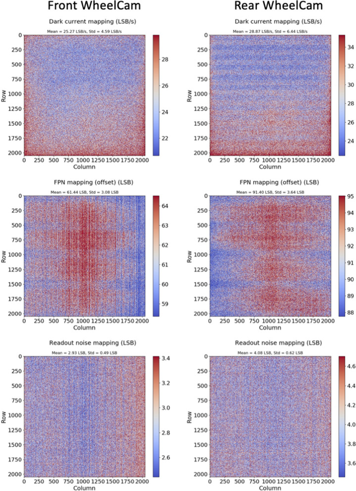
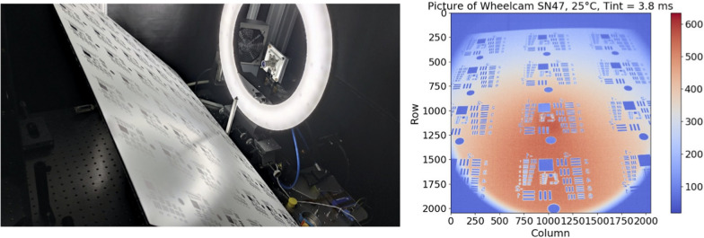
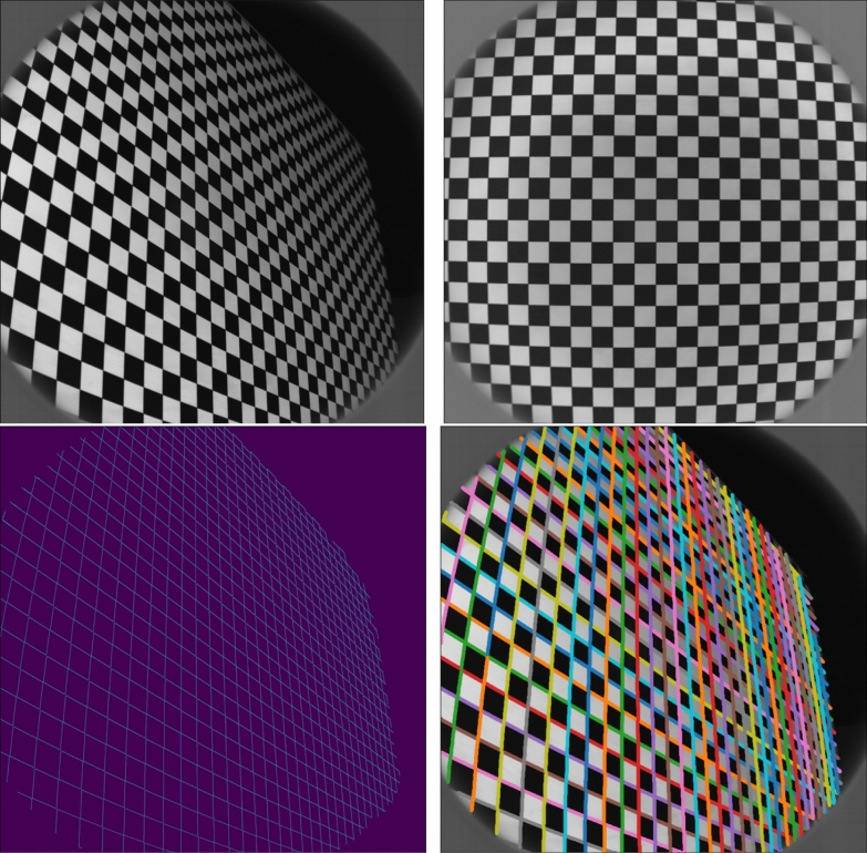
IDEFIX, the Martian Moons eXploration (MMX) mission Phobos rover, will be the first of its kind to attempt wheeled-locomotion on a low-gravity surface. The IDEFIX WheelCams, two cameras placed on the underside of the rover looking at the rover wheels, provide a unique opportunity to study the surface properties of Phobos, regolith behaviour on small-bodies and rover mobility in low-gravity. The information gained about Phobos' surface will be of high importance to the landing and sampling operations of the main MMX spacecraft, in addition to being valuable for understanding the surface processes and geological history of Phobos. Here we introduce the WheelCam science objectives, the instrument and the characterisation activities. We also discuss the on-going preparations linked to the analysis and interpretation of the WheelCam images on the surface of Phobos.

Keywords: Camera; Geotechnics; In situ imaging; Locomotion; MMX; Morphology; Phobos; Regolith; Space weathering; Terramechanics.


Conflict of interest statement

Competing interestsThe authors declare that they have no competing interest.

Figures

Fig. 1
Fig. 1
Examples of wheeled rovers on the surface of the Moon and Mars. a The Lunar Roving Vehicle (NASA) was operated during the Apollo program (Asnani et al. 2009). b The Yutu-1 rover (CNSA) was developed for the Chang’E-3 lunar mission (Li et al. 2015). The c Curiosity (Grotzinger et al. ; Vasavada 2022) and d Perseverance (Farley et al. 2020) Mars rovers developed by NASA. e The Zhurong rover developed by CNSA for the Tianwen-1 Mars mission (Mallapaty ; Ding et al. 2021b)
Fig. 2
Fig. 2
The WheelCams on IDEFIX. Left: The MMX IDEFIX rover showing the location of the two WheelCams. Right: The flight model of a WheelCam. Image credit: CNES
Fig. 3
Fig. 3
Varied particle morphologies on different planetary surfaces. a Image of rounded coarse grains present on the flank of a small ripple as oberved by Wide Angle Topographic Sensor for Operations and eNgineering (WATSON) on the NASA Mars 2020 Perseverance rover on sol 106 (image from Vaughan et al. 2023). b Apollo 16 Lunar Sample 60529 (NASA). c Large angular boulders on the surface of asteroid 101955 Bennu (OSIRIS-REx/NASA/Arizona State University). d Dust-mantled rounded particles on the surface of Mars taken by MAHLI on Mars Science Laboratory (MSL) sol 531 (NASA/JPL-Caltech/MSSS)
Fig. 4
Fig. 4
Regolith–wheel interactions. a Image taken by Opportunity while attempting to extract itself from Purgatory megaripple. The wheel penetrates deeply into the regolith and fines can be seen adhering to the rover wheel, demonstrating a very cohesive nature of the regolith. Cohesive clumps can also be seen inside the wheel trench (1f170714026esf55pcp1244l0m1.img.jpg; NASA/JPL-Caltech). b Cohesive regolith attached to the wheel of the Curiosity rover as observed by the NavCam onboard NASA’s Mars rover Curiosity on Sol 22 (NASA/JPL-Caltech)
Fig. 5
Fig. 5
Methods for estimating the bearing capacity of planetary surfaces. a Buzz Aldrin’s bootprint from the Apollo 11 mission in 1969 (NASA). b Boulder tracks on a pyroclastic deposit on the lunar surface. Image from Bickel et al. (2019). c Boulder tracks on asteroid Didymos as observed by DRACO on DART (NASA/APL/ISAE-SUPAERO; Bigot et al. 2024)
Fig. 6
Fig. 6
Rover tracks on planetary surfaces. a Spirit Rover Navcam image showing shallow rover tracks on Mars. The tracks appear dark as the bright dust cover has been disturbed by the rover (sol 127, image 2N137650599MRL4800P1846R0M1; NASA/JPL-Caltech). b Curiosity Color Mastcam mosaic showing tracks on Mars. Tracks on the bedform expose a dark subsurface material, whereas tracks on the rocky surface expose much less dark material (image PIA17944; NASA/JPL-Caltech-MSSS).c Yutu-1 rover tracks on the Moon (Chinese national space agency, CNSA; Chinese Academy of Sciences, CAS). d Opportunity rover PanCam image showing deep tracks on Mars. The brighter materials are more cohesive, leading to a better perseverance of the wheel treads and the formation of cohesive clumps (sol 447, image F4_1P167868006EFF55DIP2408L4M1; NASA/JPL-Caltech/Cornell). e Opportunity NavCam image showing the bright material subsurface material inside the tracks. The second set of tracks that are visible are more dust-mantled and were formed during the approach to the area 6 weeks prior to this image being taken (sol 491, image PIA07999; NASA/JPL-Caltech/Cornell). f Lunokhod-1 rover image showing the rovers’ tracks on the Moon. The thin line (between the two tracks) is the 9th wheel, used by the rover to measure the distance travelled (image L1_D03_S01_P02m, Soviet)
Fig. 7
Fig. 7
Extracting information about the regolith properties from rover tracks. The example track show here was made by the Curiosity rover (NASA)
Fig. 8
Fig. 8
Examples of wheel sinkage into different types of surface materials: (left) glass beads and (right) quartz sand. In both examples the load applied to the wheel is the same but the sinkage is different
Fig. 9
Fig. 9
MMX IDEFIX WheelCams. (left) WheelCam optical assembly cross section. (right) WheelCam camera definition. The optics are tilted by approximately 3 with respect to the detector
Fig. 10
Fig. 10
WheelCam field of view. The simulated field of view for the rear (left) and front (middle) WheelCams, and an image (right) from the front WheelCam qualification model taken using the ISAE-SUPAERO WheelCam testbed (see Section 5.2). In the right image the IDEFIX flight wheel is used along with Phobos regolith simulant (Miyamoto et al. 2021)
Fig. 11
Fig. 11
Thermal Vacuum Chamber acceptance test sequence for the WheelCams. During a “Full measurement”: dark, FTEO, resolution, distortion and flat measurements were made. During a “Light measurement”: dark, resolution, distortion and flat measurements were made
Fig. 12
Fig. 12
Dark measurements of the WheelCam flight models. Results for the front WheelCam are shown on the left, and results for the rear WheelCam are shown on the right. (Top) Dark current mapping (in LSB/s) at 25C. The pixel array is given with a colourbar whose intervals are [μdarkcurrent-σdarkcurrent ; μdarkcurrent+σdarkcurrent], where μdarkcurrent is the average dark current and σdarkcurrent is the standard deviation of the dark current. (Middle) The offset or FPN measurement in LSB following the same colourbar rule as the dark current measurement. (Bottom) The readout noise in LSB following the same colourbar rule as the dark current measurement
Fig. 13
Fig. 13
WheelCam resolution measurements. (left) Optical bench for WheelCam resolution measurements. (right) Example for the front WheelCam when the test pattern is at 32 cm. No corrections (radiometric, distorsion) have been applied
Fig. 14
Fig. 14
Checkerboard images and gridline detection (Top) Example checkerboard images acquired with a WheelCam. (Bottom) Grid line detection. Left: Canny edge filtering. Right: Line grouping
Fig. 15
Fig. 15
WheelCam radiometric transition model. Green: Single edge transition. Blue: Heaviside function. Orange: Convoluted Heaviside function
Fig. 16
Fig. 16
WheelCam distortion errors. Left: Front (above) and Rear (below) WheelCam Geometrical distortion model error. The radius is the distance from the center of the image i.e., (xc, yc). Right: Front (above) and Rear (below) WheelCam relative error when measuring a distance
Fig. 17
Fig. 17
Discrete Element Method simulations of rolling in Earth and Phobos gravity. (Top) Snapshot from a rolling simulation in terrestrial gravity with a wheel rotational velocity of 0.65 rad/s. The container is filled with 6 ± 0.5 mm diameter rough spherical particles. The particles are coloured by their vertical positions at the start of the simulation. (Bottom) Visualisation of the particle flow around the rover wheel after a 90 degree turn for simulations with different two different gravitational accelerations (left—Earth, right—Phobos), but the same rotational Froude number (0.05). The particle velocity vectors are coloured by v/ωrs, where rs = 77 mm, v is the velocity magnitude of the fastest moving particle, and ω is the rotational velocity of the wheel. For further details see Sunday (2022)
Fig. 18
Fig. 18
WheelCam testbed at ISAE-SUPAERO. (Top) Detailed view of the wheel assembly on the WheelCam testbed. The Wheel assembly can be lifted and lowered into place using the pulley system shown in the photo. The wheel is driven by a brushed DC motor and can translate freely in the vertical and horizontal directions. (Middle) The WheelCam LEDs as mounted on the ISAE-SUPAERO WheelCam testbed for the rear (left) and front (right) cameras. The camera supports and baffles have been 3D printed for the testbed but their form is the same as on the IDEFIX rover. The LEDs have also been mounted and positioned identically as on the IDEFIX rover. (Lower left) Rear camera perspective. (Lower right) Front camera perspective. These field of views generated by the WheelCam testbed at ISAE-SUPAERO are approximately the same as the IDEFIX WheelCam field of views. The surface material in these images is quartz sand
Fig. 19
Fig. 19
Examples of image segmentation for size and morphological characterisation. Left: Angular particles on the surface of asteroid (101955) Bennu taken by OCAMS on OSIRIS-REx (NASA/University of Arizona). Right: Image of rounded pebbles on the surface of Mars taken by MAHLI on sol 2356 of the Mars Science Laboratory Mission (NASA). The particles detected through the semi-automatic segmentation are used for morphological characterisation are shown in blue. The red particles are less-well resolved (<30 px), and should be not be used for resolution-dependant morphological parameters. For more details see Robin et al. (2024)
Fig. 20
Fig. 20
3D reconstruction algorithm. Example 3D model of the reconstructed wheel trench derived from the Structure from Motion method using images acquired with the ISAE-SUPAERO WheelCam testbed. In this example the IDEFIX wheel is rolling on quartz sand. The colour bar indicates the distance (in mm) from a given reference point
Fig. 21
Fig. 21
Linear and angular velocity determination. a The linear velocity of the rover can be determined using the apparent motion of the regolith particles (green arrows) with respect to the camera. b The angular velocity of the wheel can be determined through feature tracking of points on the IDEFIX wheel. The blue points show the tracked features, and the red dashed line is the best fit ellipse, used to calculate the homography matrix before the angular velocity determination

References

    1. Agarwal S, Senatore C, Zhang T, Kingsbury M, Iagnemma K, Goldman DI, Kamrin K (2019) Modeling of the interaction of rigid wheels with dry granular media. J Terramech 85:1–14
    1. Amsili A et al (2025) 3d reconstruction of local topography using the IDEFIX WheelCams. 2025 (in preparation)
    1. Arvidson RE, Anderson RC, Haldemann AFC, Landis GA, Li R, Lindemann RA, Matijevic JR, Morris RV, Richter L, Squyres SW, Sullivan RJ, Snider NO (2003) Physical properties and localization investigations associated with the 2003 Mars Exploration rovers. J Geophys Res: Planets 108(E12):2002JE002041. ISSN 0148-0227. 10.1029/2002JE002041
    1. Asnani V, Delap D, Creager C (2009) The development of wheels for the lunar roving vehicle. J Terrramech 46(3):89–103
    1. Attree N, Groussin O, Jorda L, Sergey Rodionov A-T, Auger NT, Brouet Y, Poch O, Kührt E, Knapmeyer M et al (2018) Thermal fracturing on comets-applications to 67p/churyumov-gerasimenko. Astron Astrophys 610:A76

LinkOut - more resources