Review
. 2025 Jul 19;15(7):467.
doi: 10.3390/bios15070467.

Graphene-Bacteriophage Hybrid Nanomaterials for Specific and Rapid Electrochemical Detection of Pathogenic Bacteria

Affiliations
Review

Graphene-Bacteriophage Hybrid Nanomaterials for Specific and Rapid Electrochemical Detection of Pathogenic Bacteria

José M Campiña et al. Biosensors (Basel). .

Abstract

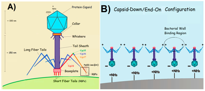
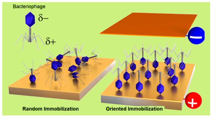
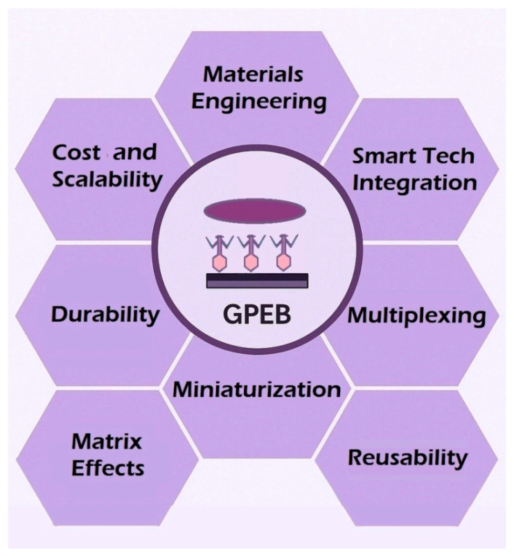
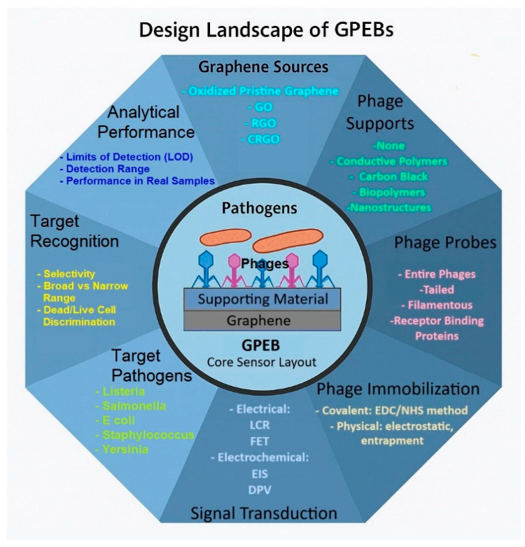
Efficient and rapid detection of bacterial pathogens is crucial for food safety and effective disease control. While conventional methods such as PCR and ELISA are accurate, they are time-consuming, costly, and often require specialized infrastructure. Recently, electrochemical biosensors integrating graphene nanomaterials with bacteriophages-termed graphages-have emerged as promising platforms for pathogen detection, offering fast, specific, and highly responsive detection. This review critically examines all electrochemical biosensors reported to date that utilize graphene-phage hybrids. Key aspects addressed include the types of graphene nanomaterials and bacteriophages used, immobilization strategies, electrochemical transduction mechanisms, and sensor metrics-such as detection limits, linear ranges, and ability to perform in real matrices. Particular attention is given to the role of phage orientation, surface functionalization, and the use of receptor binding proteins. Finally, current limitations and opportunities for future research are outlined, including prospects for genetic engineering and sensor miniaturization. This review serves as a comprehensive reference for researchers developing phage-based biosensors, especially those interested in integrating carbon nanomaterials for improved electroanalytical performance.

Keywords: bacteriophages; bioreceptor immobilization; electrochemical biosensors; graphene nanomaterials; nanomaterial–bioreceptor interfaces; pathogen detection.


Conflict of interest statement

The authors declare no conflicts of interest.

Figures

Figure 1
Figure 1
Artistic models: (A) the typical structure of a tailed bacteriophage, with receptor binding proteins (RBPs), located at the tip of the long fiber protein Gp37 (orange fragment); (B) a capsid-down (or end-on) orientation of tailed phages adsorbed onto a positively charged surface. Both illustrations are adapted with permission from P. M. V. Fernandes et al. [35]. Copyright 2023 MDPI.
Figure 6
Figure 6
Schematic illustration depicting the electrical dipole nature of tailed bacteriophages and the deposition of their films by different methods. Phages immobilized by physisorption on a neutral surface or through unspecific covalent bonding (e.g., those targeting amino acid groups) typically result in a random orientation of phage constituents (left panel). Alternatively, the charge dipole that characterizes tailed phages allows for oriented immobilization in either tail-down or capsid-down (right panel) configurations. This can be achieved by applying an electric field with desired polarization [38] or by introducing charged groups on the substrate (as shown in Figure 1B). Adapted with permission from S.J., Machera et al. [92]. Copyright 2020, MDPI.
Figure 15
Figure 15
Overview of the main bottlenecks limiting the broader implementation of GPEBs. These include challenges related to material selection, probe immobilization, sensor reusability, integration with digital systems, and operation in real-world environments. Each topic is addressed in detail in the concluding section.
Figure 2
Figure 2
Conceptual framework illustrating the characteristics of GPEBs. At the center, a graphene surface functionalized with bacteriophages represents the biosensing interface. Radiating outward, eight interconnected domains summarize the key choices observed in the reviewed literature.
Figure 3
Figure 3
Comparison of the bottom-up (A) and top-down (B) approaches for synthesizing graphene nanomaterials: (A) Atom-by-atom growth of single-layer graphene sheets from organic molecules using vapor deposition processes. (B) Various methods employed for the exfoliation of graphite.
Figure 3
Figure 3
Comparison of the bottom-up (A) and top-down (B) approaches for synthesizing graphene nanomaterials: (A) Atom-by-atom growth of single-layer graphene sheets from organic molecules using vapor deposition processes. (B) Various methods employed for the exfoliation of graphite.
Figure 4
Figure 4
Workflow of a graphene–phage electrochemical biosensor developed by Zhou et al. [58] for the detection of E. coli O157:H7 GXEC-N07. The electrode was constructed by modifying a glassy carbon electrode (GCE) with carboxyl-rich graphene oxide (CRGO), conductive carbon black (CB), EP01 phages, and Bovine Serum Albumin (BSA). The figure illustrates the biosensor fabrication, bacterial recognition process, electrochemical signal transduction (via electrochemical impedance spectroscopy, EIS), and its analytical application in raw pork and milk matrices (including recovery rates). Reproduced with permission from Elsevier Science Ltd. Copyright 2021.
Figure 5
Figure 5
Artistic model illustrating the most common approaches for the immobilization of phages on surfaces. Adapted with permission from L. O’Connell et al. [86]. Copyright 2021 American Chemical Society.
Figure 7
Figure 7
Design of the graphage-based field-effect transistor sensor reported by K. Nakama et al. for E. coli detection. The impact that pathogens captured by the rGO-M13 hybrid has on the electrical properties of the channel is also illustrated. Reprinted from [59]. Copyright 2021, Elsevier Science Ltd.
Figure 8
Figure 8
Confocal microscopy images depicting vB_YepM_ZN18 phages labeled with SYBR gold (a fluorescent nucleic acid stain) on various surfaces: (a) ITO/PI–5–CA, (b) ITO/PI–5–CA/rGO, and (c) ITO/PI–5–CA/rGO/AuNPs. FESEM images providing insights on the morphological changes of a GCE/PI-5-CA/rGO/AuNPs electrode (d), its transformation upon phage modification (e), and the subsequent capture of Y. pseudotuberculosis (f). Reprinted with permission from Q. Yang et al. [60]. Copyright 2021, Springer Nature.
Figure 9
Figure 9
Simplified schematic of the experimental setup employed by A. H. Keihan et al. for the detection of E. coli XL1-blue [61]. The system comprised two planar carbon paste electrodes (CPEs), each modified with reduced graphene oxide (rGO) and bacteriophages and functioning as the plates of a capacitor. Prior to measurements, both CPEs were incubated in E. coli dispersions for predetermined durations. Capacitive measurements were conducted using a low-frequency LCR meter, with phosphate buffer acting as the dielectric medium.
Figure 10
Figure 10
(A) Nyquist diagrams recorded using graphene-based screen-printed electrodes in the presence of 5 mM [Fe(CN6)]+3/+2 + 0.1 M PBS: unmodified electrode (wine diamonds), phage-coated electrode (green triangles), and electrodes exposed to S. arlettae at concentrations ranging from 2·102 to 2·108 CFU·mL−1 (red and green circles, black squares, yellow crosses, and black underscores). (B) Top: Charge transfer resistance (RCT) values derived from the data in (A). Bottom: Linear regression analysis of the top dataset in logarithmic format. Reprinted with permission from N.Bhardwaj et al. [51]. Copyright 2016, Elsevier Science Ltd.
Figure 11
Figure 11
Nyquist diagrams recorded in 5 mM [Fe(CN6)]+3/+2 + 0.1 M PBS using GO/phage-modified screen-printed electrodes previously incubated in the following S. enterica solutions: non-incubated (cyan squares), 10 (orange circles), 102 (blue diamonds), 104 (wine rectangles), 106 (green triangles), and 108 CFU·mL−1 (violet crosses). Adapted from Quiton et al. [56] (CC BY license). International Frequency Sensor Association (IFSA) Publishing, S.L., 2018 (available at https://sensorsportal.com/HTML/ST_JOURNAL/vol_28.html; accessed on 15 June 2024).
Figure 12
Figure 12
Resistance change % [(R − R0/R0) × 100] measured against the concentration of E. coli (host bacteria) and P. chlororaphis (control). The curves registered in the presence of E. Coli were taken with a GFET containing M13-modified (full black circles) and bare rGO channels (empty circles). R0 is the resistance measured after incubation with phosphate buffer (blank), and R is the value measured after incubation with the given bacterium (E. coli or P. chlororaphis). The control curve is shown in gray circles. The results obtained for a bacterial concentration of 106 CFU·mL−1 are better compared in the bottom chart (same color key). Reprinted with permission from K. Nakama et al. [59]. Copyright 2021, Elsevier Science Ltd.
Figure 13
Figure 13
(A) Differential pulse voltammograms (DPVs) obtained in PBS (0.1 M, pH 6.0) for the GCE/PI-5-CA/rGO/AuNPs/phage electrode after incubation with solutions of Y. pseudotuberculosis with different cell density: 0–1.05 × 10⁷ CFU·mL−1. (B) Linear relationship found between the current inhibition factor (I-I0) and the logarithm of the concentration of Y. pseudotuberculosis. (C) Control experiments performed to evaluate the selectivity of the sensor towards other pathogens at the same concentration (3.00 × 10⁶ CFU·mL−1). (D) Capability to discriminate between live (3.30 × 10⁵ CFU·mL−1), dead (3.30 × 10⁵ CFU·mL−1), and a mixture of live/dead Y. pseudotuberculosis cells (1:1). Reprinted with permission from Q. Yang et al. [60]. Copyright 2021, Springer Nature.
Figure 14
Figure 14
DPV currents obtained for a GCE/CRGO/AuNPs/RBP41 electrode incubated with different Salmonella spp. (including the target S. Typhimurium 14028) and other bacteria from different genera. All the pathogens were present at same concentration (105 CFU·mL−1). ** denotes a statistically significant difference (p < 0.01) between the blue- and orange-coded pathogens. Reprinted with permission from Y. Ding et al. [57]. Copyright 2024 Elsevier Science Ltd.

Similar articles

References

    1. Oliver H.F., Wiedmann M., Boor K.J. Environmental Reservoir and Transmission into the Mammalian Host. In: Goldfine H., Shen H., editors. Listeria Monocytogenes: Pathogenesis and Host Response. 1st ed. Springer; Boston, MA, USA: 2007. pp. 111–138. - DOI
    1. European Food Safety Authority, European Centre for Disease Prevention and Control The European Union One Health 2019 Zoonoses Report. EFSA J. 2021;19:e06406. doi: 10.2903/j.efsa.2021.6406. - DOI - PMC - PubMed
    1. Havelaar A.H., Kirk M.D., Torgerson P.R., Gibb H.J., Hald T., Lake R.J., Praet N., Bellinger D.C., De Silva N.R., Gargouri N., et al. World Health Organization Global Estimates and regional comparisons of the burden of foodborne disease in 2010. PLoS Med. 2015;12:e1001923. doi: 10.1371/journal.pmed.1001923. - DOI - PMC - PubMed
    1. Jaffee S., Henson S., Unnevehr L., Grace D., Cassou E. The Safe Food Imperative: Accelerating Progress in Low- and Middle-Income Countries. World Bank; Washington, DC, USA: 2019. (Agriculture and Food Series).
    1. Mansfield J., Genin S., Magori S., Citovsky V., Sriariyanum M., Ronald P., Dow M., Verdier V., Beer S.V., Machado M.A., et al. Top 10 plant pathogenic bacteria in molecular plant pathology. Mol. Plant Pathol. 2012;13:614–629. doi: 10.1111/j.1364-3703.2012.00804.x. - DOI - PMC - PubMed

MeSH terms

LinkOut - more resources