Case Reports
. 2025 Jul 23;30(20):104181.
doi: 10.1016/j.jaccas.2025.104181.

The Secret Life of a Lost Guidewire

Affiliations
Case Reports

The Secret Life of a Lost Guidewire

Samuel McGrath et al. JACC Case Rep. .

Abstract

Background: Lost guidewires during central venous catheterization are rare but serious, requiring prompt removal to reduce morbidity and mortality.

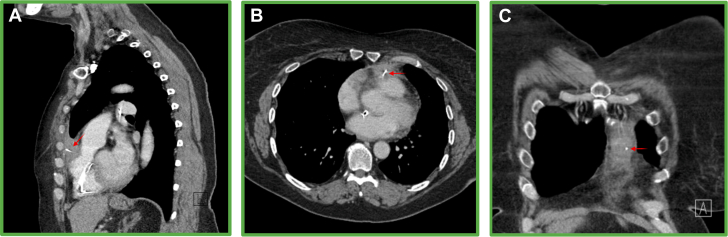
Case summary: A 58-year-old woman presented with a pulsating back mass and a spontaneous bruise under her left clavicle. More than 10 years ago, a 0.035-inch guidewire had been lost in her circulation, and retrieval attempts had failed. Computed tomography scan revealed a fragmented guidewire that had crossed into the arterial circulation through a patent foramen ovale and extended through the anterior mediastinum. After a discussion among the heart team, the decision was made to remove the wire percutaneously.

Discussion: This case highlights the risks of guidewire loss and the successful use of advanced catheter techniques for complex wire retrieval.

Take-home messages: Iatrogenic guidewire loss is associated with significant risk of morbidity and mortality, and the guidewire must be removed. A fragmented wire can be removed percutaneously by forming a free loop with an additional wire. If wire embolization is recognized during central venous catheter insertion, several bedside techniques can be attempted to rapidly correct the complication.

Keywords: CT; complication; guidewire; patent foramen ovale.


Conflict of interest statement

Funding Support and Author Disclosures Dr Samuel McGrath is undergoing a Clinical Research Training Fellowship (CRTF) funded by the British Heart Foundation (FS/CRTF/22/24187). Prof Hildick-Smith is a Proctor/Advisory to Abbott, Boston, Medtronic, and Edwards.

Figures

None
Graphical abstract
Figure 1
Figure 1
Intravascular Course of the Wire, With 4 Separate Still Images Taken From Computed Tomography of Different Slices Transverse thorax slice showing the wire crossing the atrial septum (red arrow). (A) Coronal abdominal slice. Red arrow indicates a wire within the inferior vena cava extending up into the right atrium. (B) Coronal thorax slice. Red arrow shows the wire entering the heart via the inferior vena cava, traversing the septum, and reaching the upper left pulmonary vein (yellow arrow). (C) Sagittal thorax slice. Red arrow highlights filaments of the unraveled wire within the right ventricle. Yellow arrow indicates the wire within the pulmonary venous vasculature, again confirming it has crossed the septum. (D) Transverse thorax slice. This view clearly shows the wire crossing the atrial septum.
Figure 2
Figure 2
Anterior Course of the Wire, With 3 Separate Still Images Taken From Computed Tomography of Different Slices In each respective view, the red arrow details the course of the wire within the thorax. (A) Sagittal thorax slice. The wire can be seen coursing through the right ventricular outflow tract through the pericardium, through the subcutaneous layer of chest wall coursing superiorly to lie in the left anterior superior chest wall. (B) Transverse thorax slice. The exit point of the wire from the right ventricular outflow tract into the pericardium. (C) Coronal thorax slice. This view helps visualize how high the final position of the wire is in the left anterior chest wall.
Figure 3
Figure 3
Posterior Course of the Wire, With 6 Separate Still Images Taken From Computed Tomography of Different Slices In each respective view, the red arrow details the cause of the wire within the abdomen, and the yellow arrow details the extravascular course within muscle or subcutaneous tissue. (A) Transverse thorax slice. The wire is seen exiting the heart posteriorly into the posterior basal segment of the right lower lobe. The exit point is thought to be the junction of the inferior vena cava and the right atrium. (B) Transverse thorax slice. The wire has gone beneath the diaphragm. (C) Coronal thorax slice. The exit point is via the right paravertebral soft tissues adjacent to T12. (D) Sagittal thorax slice. This view shows the wire traveling posteriorly. (E) Sagittal thorax slice. The wire is seen exiting adjacent to T12. (F) Sagittal thorax slice. The wire is seen traveling through the soft tissues to just beneath the skin.
Figure 4
Figure 4
Exteriorized Wire Looping Around the Fragmented Wire (A) An exteriorized wire being looped around the fragment within the right atrium. (B) The gooseneck snare coming out of the Agilis catheter to snare the free end of the wire.
Figure 5
Figure 5
Fragmented Guidewire After Removal The Patient asked to keep the fragment after the procedure
Figure 6
Figure 6
Conventional Snaring Methods and Hangman Technique (A) Failure of conventional snaring techniques. (B) Hangman snaring technique used in our case. (A) Step 1: A gooseneck snare fails to grip the wire fragment owing to the absence of a loose end. Step 2: A tulip (EN Snare) snare can grasp the wire, but lacks sufficient purchase on the fragments. Step 3: A catheter can hook over the wire, but the operator loses significant tactile feedback. This is difficult when applying force and increases the risk of injuring the surrounding structures. (B) Step 1: A steerable catheter of adequate French size is required to accommodate multiple instruments. The dotted line represents the free J-wire within the catheter, which is used to form the loop, and the gooseneck snare is also within the catheter. Step 2: The catheter is manipulated to hook around the wire. Step 3: The free J wire loops around the free fragment, and the catheter is retracted and straightened. Step 4: A gooseneck snare captures the loose end of the J wire, securing it around the fragment. Step 5: The snare is withdrawn into the catheter, creating a tight loop around the wire fragment. The operator applies traction by pulling the snare further into the catheter while maneuvering the catheter itself. Step 6: The wire fragment is successfully withdrawn into the catheter.

References

    1. National Institute for Clinical Excellence . 2002. Guidance on the use of ultrasound locating devices for placing central venous catheters.https://www.nice.org.uk/guidance/ta49/resources/guidance-on-the-use-of-u...
    1. Mariyaselvam M.Z.A., Patel V., Young H.E., Blunt M.C., Young P.J. Central venous catheter guidewire retention: lessons from England’s never event database. J Patient Saf. 2022;18:e387–e392. - PubMed
    1. Monaca E., Trojan S., Lynch J., Doehn M., Wappler F. Broken guide wire - a fault of design? Can J Anesth Can Anesth. 2005;52:801–804. - PubMed
    1. Jalwal G., Rajagopalan V., Bindra A., et al. Percutaneous retrieval of malpositioned, kinked and unraveled guide wire under fluoroscopic guidance during central venous cannulation. J Anaesthesiol Clin Pharmacol. 2014;30:267. - PMC - PubMed
    1. Fisher R., Ferreyro R. Evaluation of current techniques for nonsurgical removal of intravascular iatrogenic foreign bodies. Am J Roentgenol. 1978;130:541–548. - PubMed

Publication types

LinkOut - more resources