

Biomechanical effects of six internal fixation methods for distal femoral AO/OTA 33C1 fractures: finite element analysis
- PMID: 40713634
- PMCID: PMC12297776
- DOI: 10.1186/s12891-025-08996-z
Biomechanical effects of six internal fixation methods for distal femoral AO/OTA 33C1 fractures: finite element analysis
Abstract
Purpose: Using finite element analysis, to compare the stress and deformation of six different internal fixation methods for distal femoral fractures to obtain the optimal internal fixation method.
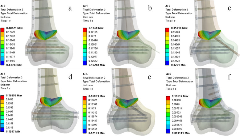
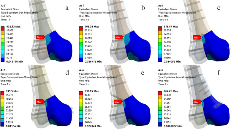
Methods: Create six groups based on different placement methods and fixation methods: 5-hole lateral plate (SP); 5-hole lateral plate + two medial screws (SP + D); 5-hole lateral plate + one trans-plate screw (SP + O); 5-hole lateral plate + one cross screw (SP + C); 5-hole lateral plate + elastic nail (SP + S); 5-hole lateral plate + medial T-shaped plate (SP + T). Observe the displacement distribution and maximum displacement at the fracture site, and stress distribution on the medial fracture fragment and internal fixation.
Results: After applying the load, mechanical indicators for internal fixation and bone blocks were obtained for all six models by finite element method. The model with a lateral single plate showed max internal fixation stress of 221.75 MPa, which was greater than other models. On the other hand, the model with a 5-hole lateral plate and medial T-shaped plate showed the smallest internal fixation stress (125.74 MPa) and the smallest total femoral deformation (0.99416 mm).
Conclusion: The combination of a 5-hole lateral plate and a medial T-shaped plate demonstrated significant biomechanical advantage compared to the other five groups. Although the 5-hole lateral plate model is slightly inferior compared to the 5-hole lateral plate and medial T-shaped plate, it remains an effective and safe fixation solution for AO/OTA 33C1 type fractures.
Keywords: Distal femur fracture; Finite element analysis; Locking Plate.
© 2025. The Author(s).
Conflict of interest statement
Declarations. Ethics approval and consent to participate: The study was approved by the Ethics Committee of the Second Affiliated Hospital and Yuying Children's Hospital of Wenzhou Medical University (approval No. 2024–K–200–01). Informed consent has been obtained from the participant. Our research adheres to the principles of the Helsinki Declaration. Consent for publication: Not applicable. Competing interests: The authors declare no competing interests.
Figures


References
-
- Kubiak EN, Fulkerson E, Strauss E, Egol KA. The evolution of locked plates. J Bone Joint Surg Am. 2006;88(Suppl 4):189–200. - PubMed
-
- Moloney GB, Pan T, Van Eck CF, Patel D, Tarkin I. Geriatric distal femur fracture: are we underestimating the rate of local and systemic complications? Injury. 2016;47(8):1732–6. - PubMed
Publication types
MeSH terms
LinkOut - more resources
Full Text Sources
Medical
