Increasing Nebulizer Spray Efficiency Using a Baffle with a Conical Surface: A Computational Fluid Dynamics Analysis
- PMID: 40722372
- PMCID: PMC12292640
- DOI: 10.3390/bioengineering12070680
Increasing Nebulizer Spray Efficiency Using a Baffle with a Conical Surface: A Computational Fluid Dynamics Analysis
Abstract
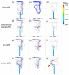
Breath-actuated nebulizers used in aerosol therapy are vital to children and patients with disabilities and stand out for their ability to accurat ely deliver medication while minimizing waste. Their performance can be measured according to the mass output and droplet size. This study aimed to analyze how the baffle impact surface geometries affect the pressure and flow streamlines inside the nebulizer using computational fluid dynamics (CFD). Computer-aided design models of conical symmetric, conical asymmetric, and arc-shaped baffle designs were analyzed using CFD simulations, with the optimal spray output validated through the differences in mass. Conical baffles exhibited superior pressure distribution and output streamlines at 0.25 cm protrusion, suggesting that the nebulizer spray performance can be enhanced by using such a conical baffle impact surface. This result serves as a valuable reference for future research.
Keywords: CFD; baffle; breath-actuated nebulizer.
Conflict of interest statement
The authors declare no conflicts of interest.
Figures


Similar articles
-
Computational Fluid Dynamics Modeling of Material Transport Through Triply Periodic Minimal Surface Scaffolds for Bone Tissue Engineering.J Biomech Eng. 2025 Mar 1;147(3):031007. doi: 10.1115/1.4067575. J Biomech Eng. 2025. PMID: 39790065
-
Comparison of the effectiveness of inhaler devices in asthma and chronic obstructive airways disease: a systematic review of the literature.Health Technol Assess. 2001;5(26):1-149. doi: 10.3310/hta5260. Health Technol Assess. 2001. PMID: 11701099
-
Management of urinary stones by experts in stone disease (ESD 2025).Arch Ital Urol Androl. 2025 Jun 30;97(2):14085. doi: 10.4081/aiua.2025.14085. Epub 2025 Jun 30. Arch Ital Urol Androl. 2025. PMID: 40583613 Review.
-
Sexual Harassment and Prevention Training.2024 Mar 29. In: StatPearls [Internet]. Treasure Island (FL): StatPearls Publishing; 2025 Jan–. 2024 Mar 29. In: StatPearls [Internet]. Treasure Island (FL): StatPearls Publishing; 2025 Jan–. PMID: 36508513 Free Books & Documents.
-
Signs and symptoms to determine if a patient presenting in primary care or hospital outpatient settings has COVID-19.Cochrane Database Syst Rev. 2022 May 20;5(5):CD013665. doi: 10.1002/14651858.CD013665.pub3. Cochrane Database Syst Rev. 2022. PMID: 35593186 Free PMC article.
References
-
- Khilnani G.C., Banga A. Aerosol therapy. Indian J. Chest Dis. Allied Sci. 2008;50:209–219.
-
- Ari A. Jet, ultrasonic, and nebulizers: An ealuation of nebulizers for better clinical outcomes. Eurasian J. Pulmonol. 2014;16:1–7. doi: 10.5152/ejp.2014.00087. - DOI
Grants and funding
LinkOut - more resources
Full Text Sources
Miscellaneous

