. 2025 Jul 14:33:102086.
doi: 10.1016/j.mtbio.2025.102086. eCollection 2025 Aug.

3D in vitro modeling of neural microenvironment through a multi-scaffold assembly approach

Affiliations

3D in vitro modeling of neural microenvironment through a multi-scaffold assembly approach

Cecilia Traldi et al. Mater Today Bio. .

Abstract

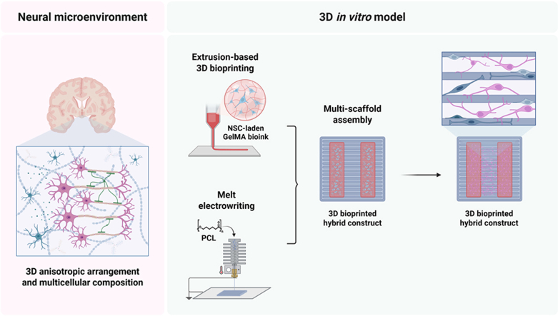
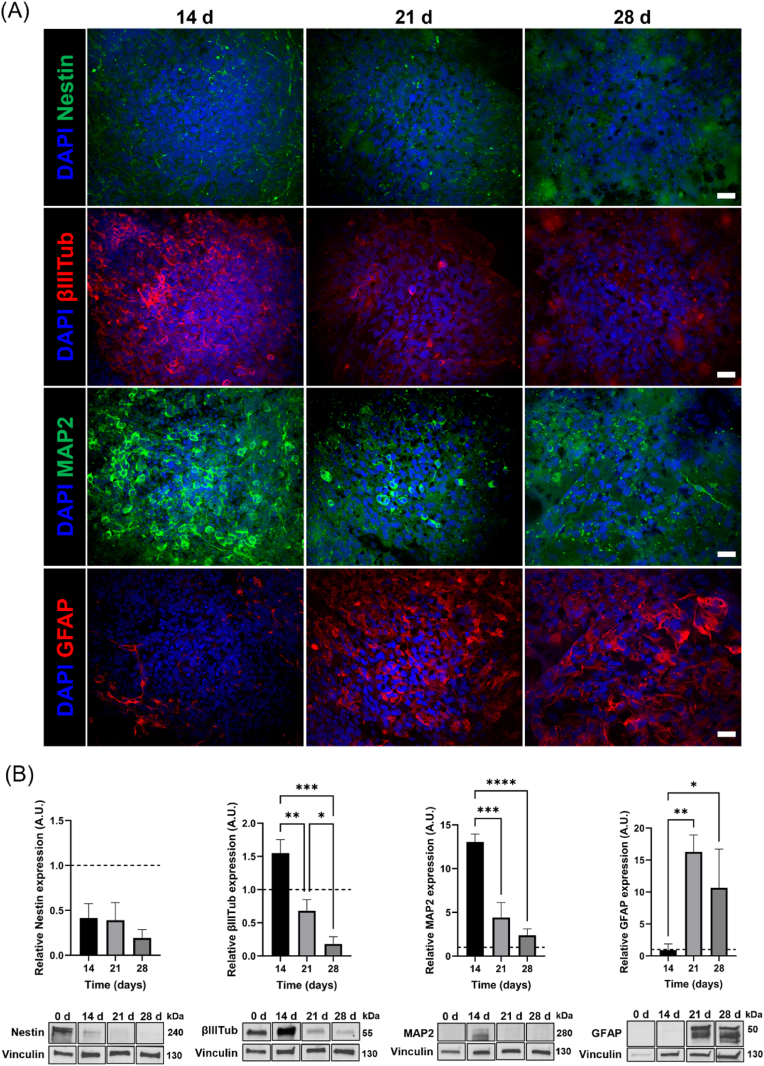
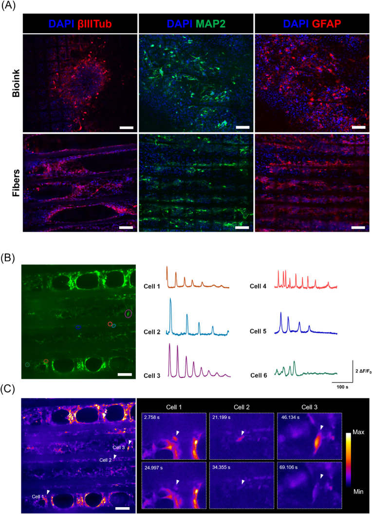
The engineering of in vitro 3D cell culture systems has emerged as promising approach to model central nervous system (CNS) intricacy with increasing physiological relevance. The fabrication of artificial microenvironments that closely resemble nervous tissue composition and architecture has provided useful substrates to promote neural cell growth and maturation under in vivo-like conditions; however, despite significant progress has been made in tissue mimicry, directing neural cell arrangement and connectivity in a controlled 3D environment remains extremely challenging. Here, we propose a novel approach that combines different biomaterials and biofabrication techniques to develop a multi-scaffold system mimicking distinctive features of the nervous tissue. Extrusion-based 3D bioprinting is employed to accurately position neural stem cells (NSCs) embedded in a gelatin methacryloyl hydrogel onto an aligned microfibrous polycaprolactone structure obtained by melt electrowriting. The hydrogel matrix successfully supports NSC growth within 3D bioprinted constructs, ensuring high cell viability and in situ NSC differentiation into neuronal and glial phenotypes. Additionally, melt electrowriting technology allows the design of a microfibrous scaffold having well-defined geometry and aligned microporosity to replicate the anisotropic characteristics of nervous tissue. The inclusion of such scaffold in the 3D bioprinted system effectively steers neural cell organization in a 3D setting, guiding neural cell elongation in a preferred direction and promoting the establishment of a functional neural network. Our approach can be used to develop more sophisticated multicellular systems, possibly reassembling specific CNS circuits within a biomimetic microarchitecture, thus offering a versatile platform for the investigation of CNS functioning and pathology.

Keywords: 3D bioprinting; Aligned topography; Melt electrowriting; Neural stem cells.


Conflict of interest statement

The authors declare the following financial interests/personal relationships which may be considered as potential competing interests: Chiara Tonda-Turo reports financial support was provided by 10.13039/501100024370Ministry of Education and Merit. If there are other authors, they declare that they have no known competing financial interests or personal relationships that could have appeared to influence the work reported in this paper.

Figures

Image 1
Graphical abstract
Fig. 1
Fig. 1
Synthesis and characterization of GelMA hydrogel. (A) (left) 1H NMR (700 MHz, D2O, 298 K) spectra of unmodified gelatin (a) and GelMA (b); (right) 1H NMR (700 MHz, D2O, 298 K) spectra of GelMA without (a) and with presaturation (b) for quantitative analysis. (B) Real-time photorheology by amplitude sweep test (i), rheological analysis by temperature ramp test (ii), frequency sweep test (iii), and viscosity as function of shear rate (iv). (C) Analysis of GelMA degradation kinetics under physiological conditions. Data are presented as mean ± SD (n = 3). One-way ANOVA with Tukey's multiple comparisons test: ∗∗∗∗p < 0.0001.
Fig. 2
Fig. 2
Fabrication of aligned microfibrous scaffold by MEW. (A) Schematics of scaffold design. (B) Dimensional analysis of samples fabricated with different sets of parameters: i (4500 V voltage, 3 % flow rate), ii (3030 V voltage, 1 % flow rate), iii (3030 V voltage, 0.8 % flow rate); data are reported as mean ± SD (n = 10). (C) Representative SEM image of MEW scaffold fabricated with the optimal set of parameters (scale bar = 50 μm). (D) Force-displacement curves obtained by uniaxial tensile test for samples stressed along a direction parallel and perpendicular to fiber alignment. (E) Comparison between stiffness in samples stressed along a direction parallel and perpendicular to fiber alignment confirming anisotropy. Data are presented as mean ± SD (n = 3). Unpaired t-test: ∗∗p < 0.01.
Fig. 3
Fig. 3
Investigation of NSC viability in 3D bioprinted constructs. (A) Representative images of LIVE/DEAD® assay in 3D bioprinted constructs (scale bar = 500 μm) and (B) semi-quantitative analysis of cell viability after 1 day from the printing process; data are reported as mean ± SD (n = 3 image fields (10X magnification) for n = 3 z-positions). Unpaired t-test: ∗∗∗∗p < 0.0001. C) Quantitative evaluation of NSC viability by CellTiter-Blue® assay up to 14 days of culture (fluorescence values are normalized to day 1) and (D) comparison of the viability profile of NSCs encapsulated in 3D bioprinted construct (3D bioprinted) and 3D GelMA hydrogels (3D hydrogel). Simple regression analysis on fluorescence values normalized to day 1. Data are presented as mean ± SD (n = 3 biological replicates). One-way ANOVA with Tukey's multiple comparisons test: ∗∗p < 0.01. (For interpretation of the references to color in this figure legend, the reader is referred to the Web version of this article.)
Fig. 4
Fig. 4
Investigation of NSC differentiation in 3D bioprinted constructs. (A) Representative immunofluorescence images for stemness-related (nestin), neuronal (βIIITub and MAP2), and astroglial (GFAP) markers in NSC-laden 3D bioprinted constructs at 14, 21, and 28 days of differentiation culture (scale bar = 20 μm). (B) Immunoblotting analysis of nestin, βIIITub, MAP2 and GFAP: protein level quantifications and representative densitometries are shown for days 14, 21, and 28 of cell differentiation. Protein levels are normalized to Vinculin (used as the loading control) and expressed relative to day 0 (dotted line). Data are presented as mean ± SD (n = 3 biological replicates). One-way ANOVA with Tukey's multiple comparisons test: ∗p < 0.05; ∗∗p < 0.01; ∗∗∗p < 0.001; ∗∗∗∗p < 0.0001.
Fig. 5
Fig. 5
Evaluation of NSC behavior in 3D bioprinted hybrid constructs. (A) Schematic description of the multi-scaffold system, comprising two bioprinted lateral neural bioink compartments and a central microfibrous compartment obtained by MEW (Created with BioRender.com). (B) Representative fluorescence images of cytoskeleton staining in cells located at the interface between bioink and microfibers, within the bioink and along microfibers after 21 days of differentiation culture (scale bar = 100 μm). (C) Distribution of neural cell orientation within the bioink and microfiber compartments. (D) Representative SEM images of neural cells on PCL microfibers after 21 days of differentiation culture (scale bar = 10 μm).
Fig. 6
Fig. 6
Development of a 3D neural network in 3D bioprinted hybrid constructs. (A) Representative immunofluorescence staining for neuronal (βIIITub and MAP2), and astroglial (GFAP) markers in hybrid constructs. Images were acquired in the different compartments of the model (scale bar = 100 μm). (B), (C) Functional characterization of 3D bioprinted hybrid constructs by calcium imaging; (B) Maximum intensity projection in time from fluorescence time-lapse recordings (left) and cell traces (right) color-coded according to circled ROIs; (C) Heatmap of fluorescence from standard deviation Z-projection in time (left) and detail of single time-lapse captures (right) showing changes in fluorescence intensity in selected arrowed cells. Images are false-colored according to fluorescence intensities as described in the calibration bar (scale bar = 100 μm). (For interpretation of the references to color in this figure legend, the reader is referred to the Web version of this article.)

Similar articles

References

    1. Rouleau N., Murugan N.J., Kaplan D.L. Functional bioengineered models of the central nervous system. Nat. Rev. Bioeng. 2023;1:252–270. doi: 10.1038/s44222-023-00027-7. - DOI - PMC - PubMed
    1. Benarroch E.E. Extracellular matrix in the CNS. Neurology. 2015;85:1417–1427. doi: 10.1212/WNL.0000000000002044. - DOI - PubMed
    1. Wedeen V.J., Rosene D.L., Wang R., Dai G., Mortazavi F., Hagmann P., Kaas J.H., Tseng W.-Y.I. The geometric structure of the brain fiber pathways. Science. 2012;335:1628–1634. doi: 10.1126/science.1215280. - DOI - PMC - PubMed
    1. Pilipović K., Harej Hrkać A., Kučić N., Mršić-Pelčić J. Modeling central nervous system injury in vitro: current status and promising future strategies. Biomedicines. 2023;11 doi: 10.3390/biomedicines11010094. - DOI - PMC - PubMed
    1. Boni R., Ali A., Shavandi A., Clarkson A.N. Current and novel polymeric biomaterials for neural tissue engineering. J. Biomed. Sci. 2018;25:1–21. doi: 10.1186/s12929-018-0491-8. - DOI - PMC - PubMed

LinkOut - more resources