. 2025 Jun 22;16(7):732.
doi: 10.3390/mi16070732.

Numerical Simulation of Hybrid Electric-Structural Control for Microdroplet Formation in Ribbed T-Junction Microchannels

Affiliations

Numerical Simulation of Hybrid Electric-Structural Control for Microdroplet Formation in Ribbed T-Junction Microchannels

Ruyi Fu. Micromachines (Basel). .

Abstract

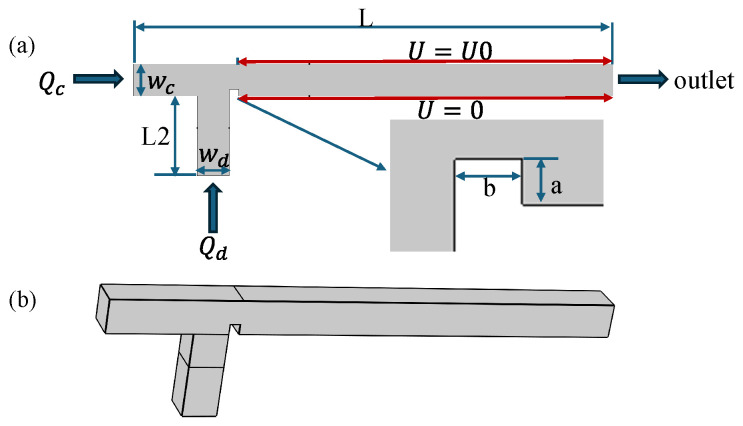
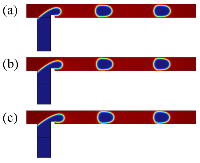
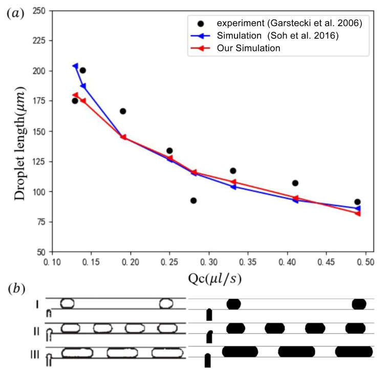
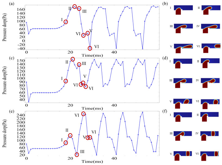
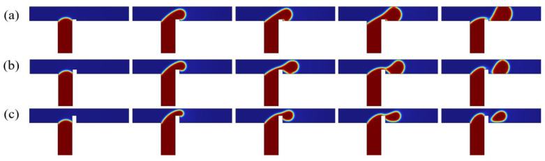
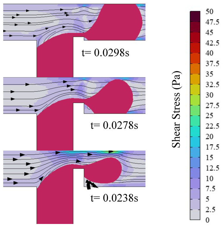
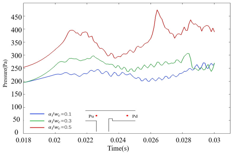
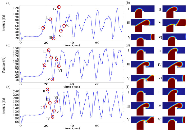
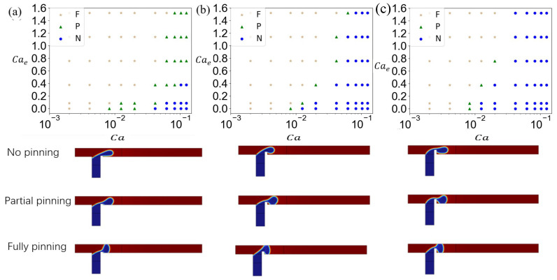
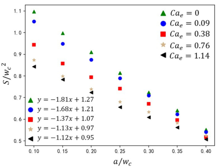
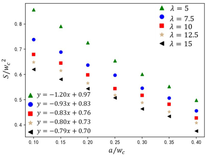
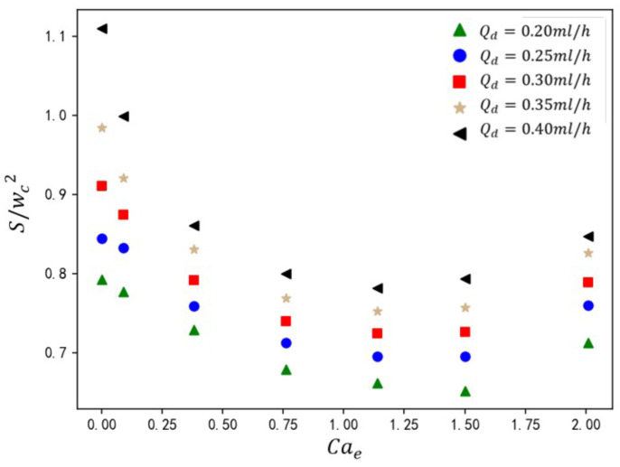
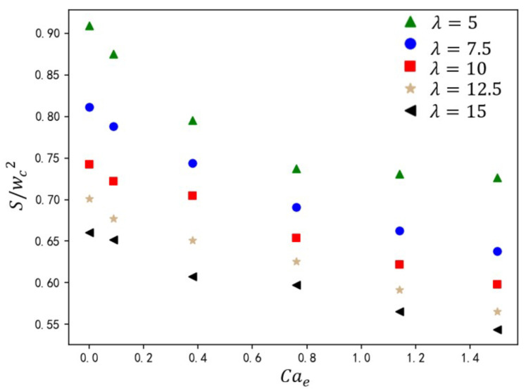
Microdroplet formation in microfluidic systems plays a pivotal role in chemical engineering, biomedicine, and energy applications. Precise control over the droplet size and formation dynamics of microdroplets is essential for optimizing performance in these fields. This work explores a hybrid control strategy that combines an active electric field with passive rib structures to regulate the droplet formation in a ribbed T-junction microchannel under an electric field. Numerical simulations based on the phase-field method are employed to analyze the effects of the electric capillary number Cae and rib height a/wc on the droplet formation mechanism. The results reveal that increasing Cae induces three distinct flow regimes of the dispersed phase: unpinning, partially pinning, and fully pinning regimes. This transition from an unpinning to a pinning regime increases the contact area between the wall and dispersed phase, restricts the flow of the continuous phase, and induces the shear stress of the wall, leading to a reduction in droplet size with the enhanced Cae. Furthermore, an increase in rib height a/wc enhances the shear stress of the continuous phase above the rib, causing a progressive shift from a fully pinning to an unpinning regime, which results in a linear decrease in droplet size. A new empirical correlation is proposed to predict droplet size S/wc2 as a function of rib height a/wc and two-phase flow rate ratio Qd/Qc: S/wc2=(-0.62-1.8Qd/Qc)(a/w)+(0.64+0.99Qd/Qc).

Keywords: electric field; microdroplet formation; microdroplet size; ribbed T-junction.


Conflict of interest statement

The author declares no conflicts of interest.

Figures

Figure 1
Figure 1
(a) Schematic of a ribbed T-junction microchannel under an electric field. Inlet figure: a schematic diagram of a rib with the width of b and height of a. (b) 3D schematic diagram.
Figure 2
Figure 2
Effect of grid size on the volume fraction of the dispersed phase: (a) grid size 9843; (b) grid size 13,105; (c) grid size 18,468.
Figure 3
Figure 3
Grid independence study with Qd=0.3 mL/h and Qc=0.9 mL/h. V1 and V2 represent the velocity along the y-direction at x=100 μm and x=150 μm, respectively.
Figure 4
Figure 4
(a) Comparison of the droplet length from the experiment [20] and simulation [46] at Qd=0.14 μLs1 under different Qc; (b) visualization of droplet formation from experiments [20] (left) and our simulations (right) under (I) Qd=0.004 μLs1, Qc=0.028 μLs1; (II) Qd=0.14 μLs1, Qc=0.139 μLs1; (III) Qd=0.111 μLs1, Qc=0.028 μLs1.
Figure 5
Figure 5
Comparison of the relationship of the deformation parameter and electrocapillary number between the current method and those of Sherwood [47] and Hua et al. [48].
Figure 6
Figure 6
Time evolution of the dispersed-phase volume fraction distribution at three electric capillary numbers (a) Cae=0, (b) Cae=0.38, and (c) Cae=1.14, where Ca=0.036, Q=3, a/wc=0.2, and b/wc=0.3.
Figure 7
Figure 7
Shear stress and streamline distribution in the microchannel, with the red line representing the isosurface of the dispersed-phase volume fraction (ϕ=0.5), where Ca=0.036, Q=3, a/wc=0.2, and b/wc=0.3. Cae=0 (up), Cae=0.38 (middle), and Cae=1.14 (down).
Figure 8
Figure 8
The variation in upstream pressure over time in the microchannel under different voltage conditions, where the dashed line represents the connection of the extreme value points, and the red dots indicate the locations of the upstream pressure points. Red markers denote measurement locations of Pu and Pd.
Figure 9
Figure 9
The evolution of the channel pressure drop over time under different electric capillary numbers (Cae) and the corresponding dispersed-phase morphology. (a,b) Cae=0; (c,d) Cae=0.38; (e,f) Cae=1.14.
Figure 10
Figure 10
Evolution of dispersed-phase volume fraction over time for different rib heights, where Ca=0.02, Q=1.67, Cae=0.38, and b/wc=0.3. a/wc=0.1 (a); a/wc=0.3 (b); a/wc=0.5 (c).
Figure 11
Figure 11
Shear stress and streamline distribution in the microchannel, with the red line representing the iso-contour of dispersed-phase volume fraction (ϕ=0.5), where Ca=0.02, Q=1.67, Cae=0.38, and b/wc=0.3. a/wc=0.1(up); a/wc=0.3 (middle); a/wc=0.5 (down).
Figure 12
Figure 12
The graph of upstream pressure variation over time under different rib height ratios in the microchannel. The blue line represents the case of a/wc=0.1; the green line represents the case of a/wc=0.3; the red line represents the case of a/wc=0.5.
Figure 13
Figure 13
The evolution of the channel pressure drop over time under different rib height ratios (a/wc) and the corresponding dispersed-phase morphology. (a,b) a/wc=0.1; (c,d) a/wc=0.3; (e,f) a/wc=0.5.
Figure 14
Figure 14
The flow state diagram of the dispersed phase in a T-junction microchannel with different rib height ratios and the corresponding flow behavior. (a) a/wc=0.1, (b) a/wc=0.3, and (c) a/wc=0.5. Different symbols represent different flow states: stars (★) represent fully pinning (F), triangles (△) represent partially pinning (P), and circles (∘) represent unpinning (N).
Figure 15
Figure 15
The effect of rib height ratio on droplet size under different electric capillary numbers. The straight-line equation in the lower-left corner represents the fitting formula for the calculated data under different electric capillary numbers, where y represents the droplet size S/wc2 and x represents the rib height ratio a/wc.
Figure 16
Figure 16
The effect of rib height ratio on droplet size under different dispersed-phase flow rates. The straight-line equation in the lower-left corner represents the fitting formula for the calculated data under different electric capillary numbers, where y represents the droplet size S/wc2 and x represents the rib height ratio S/wc2.
Figure 17
Figure 17
The effect of rib height ratio on droplet size under different viscosity ratios. The straight-line equation in the lower-left corner represents the fitting formula for the calculated data under different electric capillary numbers, where y represents the droplet size S/wc2 and x represents the rib height ratio a/wc.
Figure 18
Figure 18
The effect of electric capillary number on droplet size at different dispersed-phase flow rates.
Figure 19
Figure 19
The effect of electric capillary number on droplet size at different viscosity ratios.

Similar articles

References

    1. Chong W.H., Huang Y., Wong T.N., Ooi K.T., Zhu G.P. Magnetic nanorobots, generating vortexes inside nanoliter droplets for effective mixing. Adv. Mater. Technol. 2018;3:1700312. doi: 10.1002/admt.201700312. - DOI
    1. Yakimov A.S., Denisov I.A., Bukatin A.S., Lukyanenko K.A., Belousov K.I., Kukhtevich I.V., Esimbekova E.N., Evstrapov A.A., Belobrov P.I. Droplet Microfluidic Device for Chemoenzymatic Sensing. Micromachines. 2022;13:1146. doi: 10.3390/mi13071146. - DOI - PMC - PubMed
    1. Zheng L., Liu X., Yang G., Liu J., Jiang B., Liu Y., Li X., Hu X., Zhang Z. Highly efficient synthesis of cyclic carbonates via deep eutectic solvents from CO2 at the gas-liquid interface of microdroplet under atmospheric pressure condition. Chem. Eng. Sci. 2024;289:119867. doi: 10.1016/j.ces.2024.119867. - DOI
    1. Avesar J., Arye T.B., Levenberg S. Frontier microfluidic techniques for short and long-term single cell analysis. Lab Chip. 2014;14:2161–2167. doi: 10.1039/C4LC00013G. - DOI - PubMed
    1. Liu D., Sun M., Zhang J., Hu R., Fu W., Xuanyuan T., Liu W. Single-cell droplet microfluidics for biomedical applications. Analyst. 2022;147:2294–2316. doi: 10.1039/D1AN02321G. - DOI - PubMed

LinkOut - more resources