

Electro-Mechanical Properties of Metallized Sodium Alginate Foils at the Limit of the Electrical Conduction
- PMID: 40757360
- PMCID: PMC12311676
- DOI: 10.1021/acsomega.5c04447
Electro-Mechanical Properties of Metallized Sodium Alginate Foils at the Limit of the Electrical Conduction
Abstract
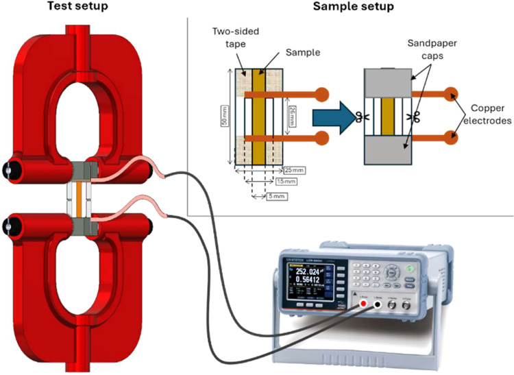
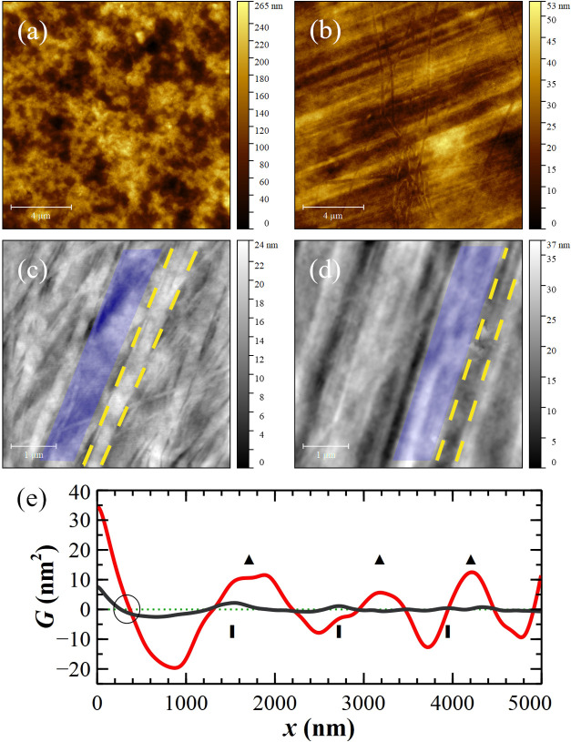
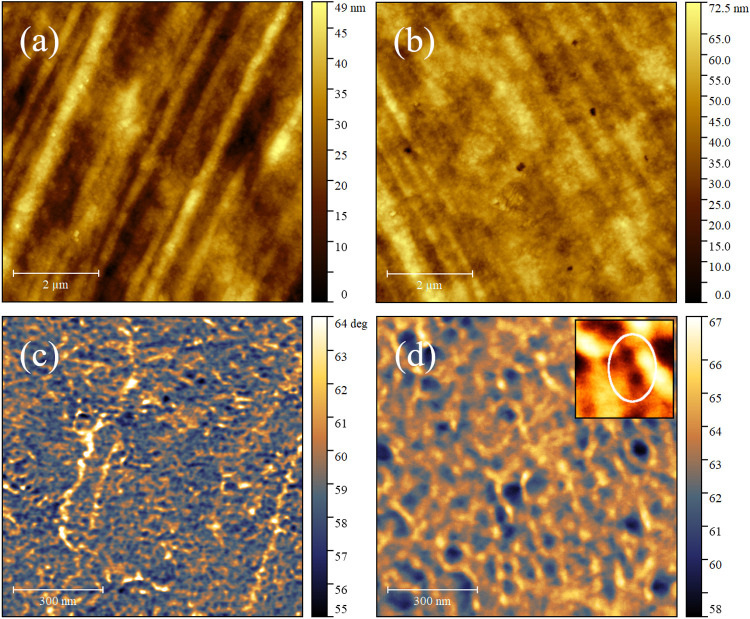
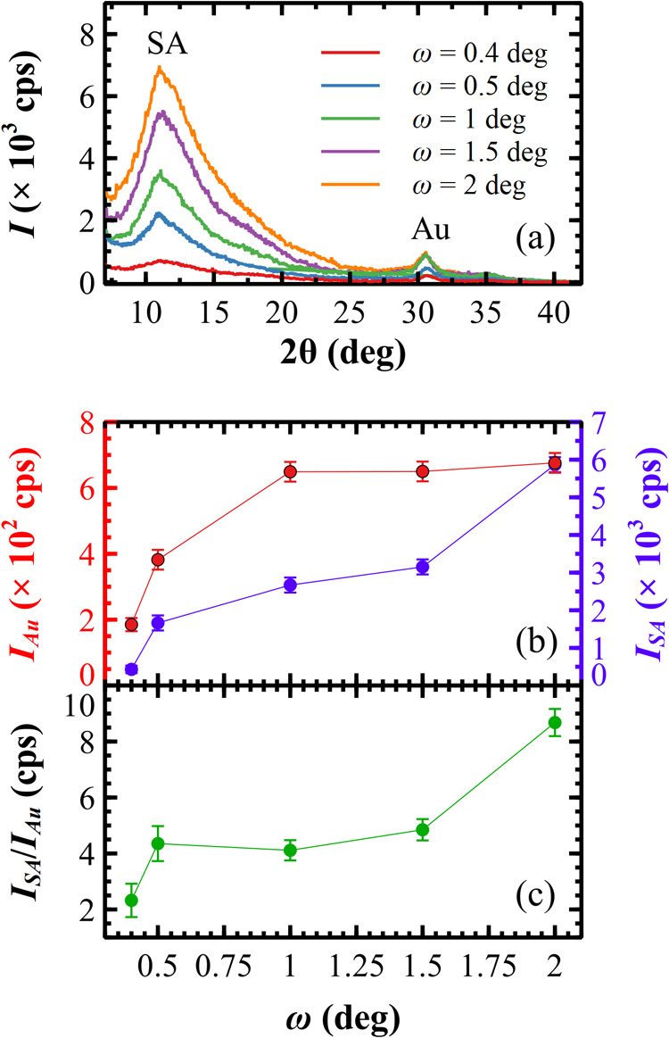
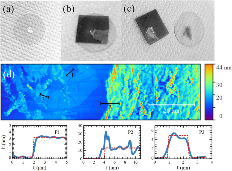
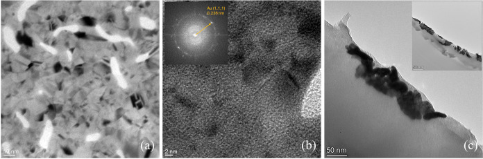
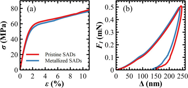
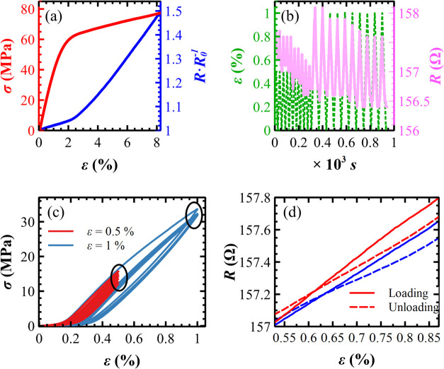
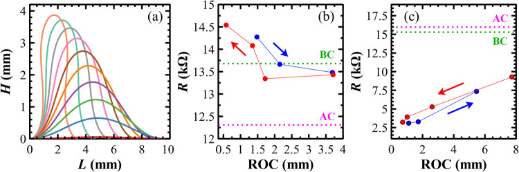
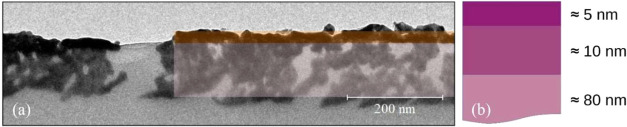
In recent years, much attention has been given to biopolymers and renewable raw materials obtained from nature to find alternatives to petroleum-based materials. In this context, we developed a free-standing and flexible conductive substrate by sputtering a thin layer of gold onto a foil of sodium alginate, producing conductive self-standing substrates. These substrates have been utilized for the fabrication of eco-designed solution-processed optoelectronic devices. Herein, we report experimental work to study the mechanism behind the dependence of electrical resistance on the mechanical deformation. Data obtained from mechanical measurements, such as strain, stress, deformation, and bending, are correlated with morphological (Atomic Force Microscopy and Transmission Electron Microscopy) and structural (X-ray Diffraction) data relative to both the surface and the subsurface regions of the metallized substrates. Collectively, these data enabled the elucidation of both the composition and spatial distribution of the metal clusters implanted within the polymer matrix. The substrates present an anisotropic Young modulus, making them more stretchable in-plane with respect to out-of-plane. In the elastic regime, the reproducibility of the electrical resistance variations with respect to the stress applied makes these substrates robust candidates for the realization of strain sensors.
© 2025 The Authors. Published by American Chemical Society.
Figures
Similar articles
-
Short-Term Memory Impairment.2024 Jun 8. In: StatPearls [Internet]. Treasure Island (FL): StatPearls Publishing; 2025 Jan–. 2024 Jun 8. In: StatPearls [Internet]. Treasure Island (FL): StatPearls Publishing; 2025 Jan–. PMID: 31424720 Free Books & Documents.
-
Management of urinary stones by experts in stone disease (ESD 2025).Arch Ital Urol Androl. 2025 Jun 30;97(2):14085. doi: 10.4081/aiua.2025.14085. Epub 2025 Jun 30. Arch Ital Urol Androl. 2025. PMID: 40583613 Review.
-
The Black Book of Psychotropic Dosing and Monitoring.Psychopharmacol Bull. 2024 Jul 8;54(3):8-59. Psychopharmacol Bull. 2024. PMID: 38993656 Free PMC article. Review.
-
Group-based interventions to reduce gambling involvement among male football fans: a synopsis of findings from a feasibility study.Public Health Res (Southampt). 2025 Jul;13(6):1-24. doi: 10.3310/SWWP9393. Public Health Res (Southampt). 2025. PMID: 40690427
-
Comparison of Two Modern Survival Prediction Tools, SORG-MLA and METSSS, in Patients With Symptomatic Long-bone Metastases Who Underwent Local Treatment With Surgery Followed by Radiotherapy and With Radiotherapy Alone.Clin Orthop Relat Res. 2024 Dec 1;482(12):2193-2208. doi: 10.1097/CORR.0000000000003185. Epub 2024 Jul 23. Clin Orthop Relat Res. 2024. PMID: 39051924
References
-
- Getahun M. J., Kassie B. B., Alemu T. S.. Recent Advances in Biopolymer Synthesis, Properties, & Commercial Applications: A Review. Process Biochem. 2024;145:261–287. doi: 10.1016/j.procbio.2024.06.034. - DOI
-
- Manoukian, O. S. ; Sardashti, N. ; Stedman, T. ; Gailiunas, K. ; Ojha, A. ; Penalosa, A. ; Mancuso, C. ; Hobert, M. ; Kumbar, S. G. . Biomaterials for Tissue Engineering and Regenerative Medicine; Narayan, R. B. , Ed.; Elsevier: Oxford, 2019; pp 462–482.
-
- Prosa M., Sagnella A., Posati T., Tessarolo M., Bolognesi M., Cavallini S., Toffanin S., Benfenati V., Seri M., Ruani G., Muccini M., Zamboni R.. Integration of a Silk Fibroin Based Film as a Luminescent Down-Shifting Layer in ITO-Free Organic Solar Cells. RSC Adv. 2014;4(84):44815–44822. doi: 10.1039/C4RA08390C. - DOI
-
- Rehm, B. H. A. ; Moradali, M. F. . Alginates and Their Biomedical Applications; Springer, 2018; Vol. 11.
-
- Samir A., Ashour F. H., Hakim A. A. A., Bassyouni M.. Recent Advances in Biodegradable Polymers for Sustainable Applications. npj Mater. Degrad. 2022;6(1):68. doi: 10.1038/s41529-022-00277-7. - DOI
LinkOut - more resources
Full Text Sources