. 2025 Aug 1;66(11):13.
doi: 10.1167/iovs.66.11.13.

In Vivo Cone Photoreceptor Topography of the Human Foveola

Affiliations

In Vivo Cone Photoreceptor Topography of the Human Foveola

Julius Ameln et al. Invest Ophthalmol Vis Sci. .

Abstract

Purpose: To study in vivo cone topography of the normal human foveola.

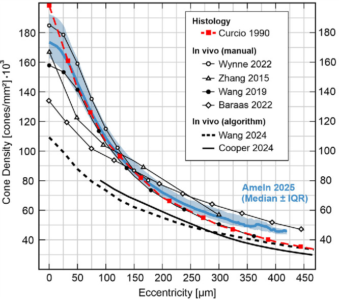
Methods: The fovea in both eyes of 30 healthy participants was imaged with adaptive optics scanning light ophthalmoscopy. High-resolution image montages spanning two degrees of visual angle were created and cone center locations annotated. Continuous cone density maps were computed by a Voronoi cell area approach to also yield the topographical center, the cone density centroid (CDC). Cone density profiles were extracted and fit with a four-parameter decay function, D = D0 / (1 + (E/a)b)c, with D as cone density (cones/mm2), D0 as cone density at the CDC, and E as eccentricity (µm).

Results: Across eyes, D0 was 175,474 ± 20,543 cones/mm2, on average (range 136,001-216,209 cones/mm2). Density dropped anisotropically along the meridians, shallower horizontally, with average best fit parameters (a, b, c) of 61.95, 2.469, 0.268 for horizontal, and 59.11, 2.012, 0.357, for vertical profiles, respectively. In radially averaged profiles, cone density reached 50% of D0 at 151 ± 17 µm eccentricity (range 128-193 µm). Temporal cone density was slightly higher than nasal. Most topographical metrics were highly correlated between fellow eyes.

Conclusions: Despite a 1.6-fold range in absolute cone density, foveolar density profiles could be well described by a sigmoidal decay function across all eyes. This established a normative cone density profile of the healthy foveola. It allowed cone density estimation in cases of only partially available data, which alleviates resolution demands for future studies and renders possible retrospective analyses of foveolar cone topography in sub-optimal imagery.


Conflict of interest statement

Disclosure: J. Ameln, None; J.L. Witten, Zeiss (E); A. Gutnikov, None; V. Lukyanova, None; F.G. Holz, Acucela (C, F), Alcon (C), Alexion (C), Alzheon (C), Apellis (C, F), Bayer (C, F), Boehringer-Ingelheim (C), Genentech/Roche (C, F), 4D Molecular Therapeutics (C), Geuder (C), Grayburg Vision (C), Heidelberg Engineering (C), Astellas (C, F), Lin Bioscience (C), Janssen (C), Novartis (C, F), Oculis (C), Oxurion (C), Science Corporation (C, F), Stealth Biotherapeutics (C), Zeiss (C, F), Allergan (C, F), Belite Bio (F), Bioeq (F), Geuder (F), NightStarx (F), Optos (F); W.M. Harmening, RhyGaze (C)

Figures

Figure 1.
Figure 1.
Cone density mapping from AOSLO images. (A) Fundus image with foveal AOSLO montage location (magenta outline) and AOSLO field of view (white square). Nine to eighteen overlapping AOSLO videos were used to create a continuous montage of the foveal center. White circle in the montage is the 2° diameter. White outlines at 0, 120, and 260 µm eccentricity are magnified below and show exemplary cone center annotations. (B) Density map computed from fully annotated montages. Color is cone density. Contour lines indicate 10% iso-density contour steps with the thick white line representing the top 20% density contour. A red-white circle marks the location of the cone density centroid (CDC), representing the topographical center of the density map and center of the foveola.
Figure 2.
Figure 2.
Foveolar cone density profiles. (A) Cone density profiles for horizontal (orange) and vertical (blue) meridional sectors. Inferior and nasal retina is shown on the left, superior and temporal retina on the right. (B) Radially averaged cone density profiles. (C) Meridional profiles normalized by D0. (D) Normalized radially averaged profiles. In all panels, individual data are thin lines, group average and standard deviation are the thick lines and shaded areas.
Figure 3.
Figure 3.
Density profile modeling. (A) Radial (black), horizontal (orange), and vertical (blue) average density profiles of 30 left eyes were fitted by a four-parameter sigmoid decay function (see Methods and Table 2). (B) Errors are calculated as the difference between individual cone densities and their individually fitted profile function. The line represents the group's average error, shaded regions denote ±1 standard deviation.
Figure 4.
Figure 4.
Circular density distribution and rugosity analysis. (A) Radial cone density profiles were extracted from the cone density map at various eccentricities (15, 40, 65, 90, 115, 140, 165, 190, 215, and 240 µm, indicated by the dark blue to light green circles). Shown here in grayscale is the average cone density map of 30 left eyes in fundus orientation. The CDC is marked by a red-white circle. (B) Radial profiles were normalized by D0 and used to find peaks (yellow and red) and troughs (light and dark blue). White circles mark the half-height between neighboring peaks and troughs and define their respective widths. One such profile, at 115 µm eccentricity, is indicated in A and B as an example. (C) Peak and trough widths analyzed across all eyes. Shaded areas are interquartile ranges (omitted for better visibility for similar superior and nasal data). (D) Rugosity, defined as the ratio of trough to peak widths, per eccentricity as boxplots. (E) Radial peak and trough positions of left (OS) and right (OD) eyes at 115 µm eccentricity.
Figure 5.
Figure 5.
Fellow-eye correlations. (A) Fellow-eye correlation of D0. (B) Number of cones in a circle (radius = 75 µm, black) and two ring shapes (ring1: inner radius 75 µm, outer radius 150 µm, dark green; and ring2: inner radius 150 µm, outer radius 225 µm, light green) around the CDC. (C, D) Maximum slope and inflection point of the horizontal (orange) and vertical (blue) profiles. (E) Iso-density contour area (ISOA) covered by the top 20% cone densities values. (F) Aspect ratio of the horizontal/vertical diameter for a contour of the mean density at 115 µm eccentricity. In all panels, left eyes (OS) are on the abscissa. All correlations display statistical significance (F-test, P < 0.001).
Figure 6.
Figure 6.
Correlation of central cone density, D0, with topographical metrics. (A, B) Correlations of the density z-score and number of cones in a circular and two ring areas around the CDC (analysis areas as described in Fig. 5) with D0. (C) Horizontal (orange) and vertical (blue) profile slope correlation with D0. All correlations display statistical significance (F-test, P < 0.001).
Figure 7.
Figure 7.
Estimation of cone density in incomplete imagery. (A) In 57 eyes, central circular image areas and their data were occluded (gray disk, example radius 75 µm). (B) To recover radial profiles, first D0 was estimated based on the individual eye's average density z-score in a 50 µm ring adjacent to the occlusion radius (cyan line). Then the full profile was estimated via fitting our profile model to the visible data and the estimated D0. (C) Absolute estimation error of D0 for different occlusion radii. (D) Median (thick lines) and 16th to 84th percentile (colored area) profile estimation error within the occlusion zone.
Figure 8.
Figure 8.
Ex vivo and in vivo foveolar cone topography compared. The current standard, histology, is the red dashed line with square markers (n = 7). In vivo data, using cone center annotation including manual corrections (lines with different markers, see legend), or other algorithmic approaches (solid or dashed lines without markers), are based on different numbers of eyes (compare Table 1). Our data is represented by the thick blue line with the shaded area indicating the interquartile range (n = 30).

Similar articles

Cited by

References

    1. Provis JM, Dubis AM, Maddess T, Carroll J. Adaptation of the central retina for high acuity vision: cones, the fovea and the avascular zone. Prog Retin Eye Res. 2013; 35: 63–81. - PMC - PubMed
    1. Bringmann A, Syrbe S, Görner K, et al.. The primate fovea: Structure, function and development. Prog Retin Eye Res. 2018; 66: 49–84. - PubMed
    1. Østerberg G. Topography of the Layer of Rods and Cones in the Human Retina: Supplementum. Acta Ophthalmol. 1935.
    1. Yuodelis C, Hendrickson A. A qualitative and quantitative analysis of the human fovea during development. Vision Res. 1986; 26: 847–855. - PubMed
    1. Tuten WS, Harmening WM. Foveal vision. Curr Biol. 2021; 31(11): R701–R703. - PubMed

LinkOut - more resources