. 2025 Aug 14;70(16):165020.
doi: 10.1088/1361-6560/adf8ac.

Beam intensity and stability control on a modified clinical linear accelerator for FLASH irradiation

Affiliations

Beam intensity and stability control on a modified clinical linear accelerator for FLASH irradiation

Yuewen Tan et al. Phys Med Biol. .

Abstract

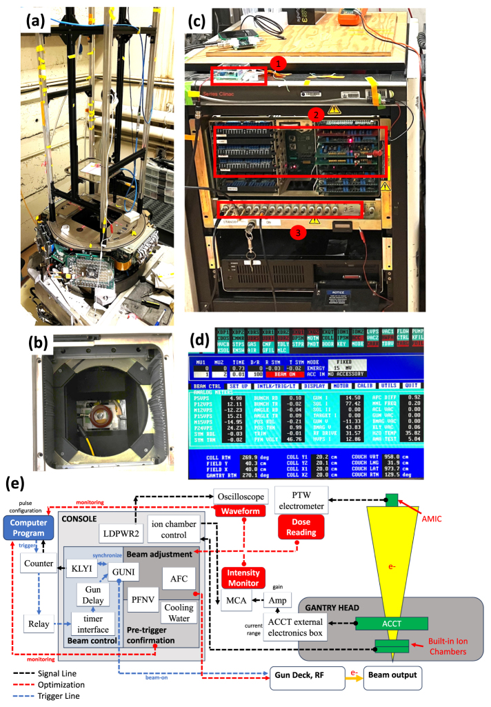
Objective.The FLASH effect has gained significant attention in radiobiology and radiation oncology due to its potential to improve therapeutic outcomes by delivering ultra-high dose-rate (UHDR) irradiations. Understanding UHDR biological mechanisms can also contribute to the development of biodosimetry and radiological medical countermeasures. However, achieving stable and reproducible high-current UHDR electron beams has been reported to be challenging with modified clinical linear accelerator (Linac) systems, and has not been systematically studied.Approach.We investigated how key standing-wave linear accelerator parameters, including electron gun current, pulse-forming network voltage, and auto-frequency control, affect the stability of electron beam intensity on a modified Varian Clinac 2100 C. We also developed a parameter-tuning method to adjust beam intensity and improve beam stability.Main results.This approach enabled (1) fine-tuning of dose-per-pulse without modifying the physical setup and (2) reduction of beam fluctuations, particularly during cold starts. These improvements enhanced both pulse-by-pulse stability and trial-by-trial reproducibility. The resulting stability was validated through multiple biological experiments.Significance.This work offers practical guidance for improving UHDR beam stability and reproducibility, as well as enabling intensity tuning in modified clinical linear accelerators. It can support the development of more reliable preclinical FLASH irradiators, thereby contributing to the advancement of FLASH research.

Keywords: FLASH-RT; UHDR beam stability; UHDR repeatability; clinical linac; electron irradiation; modified linac; ultrahigh dose rate.


Figures

Figure 1.
Figure 1.
(a) The optical rail experiment platform was mounted on the gantry head, oriented at 180, where the beam points up vertically. The crosshair sample holder can move along the rail to achieve a specific SSD, with a laser crosshair used for precise sample alignment. (b) The ACCT detector is installed inside the gantry head, positioned on top of an aluminum holder directly above the built-in ionization chamber. (c) Console at the accelerator control room. The beam triggering module, PCB card deck, and analog signal panel are highlighted in the picture and labeled 1, 2, and 3, respectively. (d) Screen in service mode. Analog signals are displayed for parameter adjustment and beam operation. This specific screenshot displays the optimal parameters for 15 MV mode. (e) Schematic diagram of essential components for beam control, monitoring, and optimization.
Figure 2.
Figure 2.
The signals were measured using a digital oscilloscope at the analog signal panel of the console. The signals were triggered and aligned by the 180 Hz SYNC signal (top, black) as a reference. Desynchronized (top, red dotted) and synchronized (top, red dashed) GUNI were compared with the KLYI (top, blue). When the GUNI and KLYI overlap, the RF power accelerates the electrons. The beam current waveforms of 15 MV mode (bottom, red solid) were collected from the ACCT detector, together with its corresponding LDPWR2 waveform (bottom, blue). The beam current signals were integrated by an amplifier of shaping time 3 µs, and the heights of amplified signals (bottom, red dotted) were collected using a multi-channel analyzer as a measure of beam pulse energy. The three dips of the LDPWR2 waveform characterized the energy dissipation in the accelerator cavities due to the choice of RF frequency, and determined the shape of the beam output, which were further optimized.
Figure 3.
Figure 3.
DPP control map as a function of PFNV and GUNI with isodose contours and optimal operational window. The measurements were taken at an SSD of 170 cm using the 16 MeV (left) and 15 MV (right) modes. For DPP values less than 200 mGy, where the ion pair recombination has no significant effect, ACCT and AMIC were used for measurements and verification, while for higher DPP values, Gafchromic films and ACCT were employed. Parameters in the optimal operational windows produce a high-intensity beam while being practically highly reproducible.
Figure 4.
Figure 4.
Maximum DPP at various SSDs. Both axes were plotted on log scale. Each data points were measured by a Gafchromic film inserted between water equivalent polyethylene slabs at depth of 1 cm and irradiated by the 15 MV beam (GUNI = 14.50 and PFNV = 46.79, triggered within the optimal triggering window). The measurement data points were either fitted by the shifted power function or inverse square function of the SSD. The fitting function is DPP=45410(SSD4)2.66 for the power function, and DPP=1190(SSD20.5)2 for the shifted inverse square function, where DPP and SSD are in units of Gy and cm, respectively.
Figure 5.
Figure 5.
Lateral dose profiles at SSDs of 35, 60, 100, and 170 cm and depths of 1 and 2 cm of phantom in 15 MV mode. The blue and red regions indicate the dose region above 90% and 95% maximum, respectively.
Figure 6.
Figure 6.
Axial PDD at SSDs of 35, 60, 100, and 170 cm using 15 MV mode, and SSD of 170 cm using 16 MeV mode. Each data point was read from the averaged film dose in a 5 mm circular region, centered at the axial location of each film. The error bars were the combination of 5% uncertainties of film reading and dose variance in the target region.
Figure 7.
Figure 7.
Top: beam currents and corresponding LDPWR2 waveforms using various AFC values from +1 to +8. These values are in arbitrary units based on the programmable AFC potentiometer increments. Bottom left: total charge of a beam pulse using various AFC values. Bottom right: pulse height distributions of 40 pulses of different beam settings.
Figure 8.
Figure 8.
Overall mean beam intensity variation for each biological experiment using 9 MeV (top) and 15 MV modes (bottom). The plots primarily focus on the beam intensities of UHDR irradiation (under 40 pulses). The horizontal axis indicates the index of the UHDR experiment in time order. Before March 2024, all the UHDR irradiations were performed by the 9 MeV beam; after that, the 15 MV beam was used. The highlighted area is where we started to implement the most recent operational procedure for 15 MV mode.

Similar articles

References

    1. Ashraf M R, Rahman M, Cao X, Duval K, Williams B B, Hoopes P J, Gladstone D J, Pogue B W, Zhang R, Bruza P. Individual pulse monitoring and dose control system for pre-clinical implementation of FLASH-RT. Phys. Med. Biol. 2022;67:095003. doi: 10.1088/1361-6560/ac5f6f. - DOI - PMC - PubMed
    1. Borca V C, Pasquino M, Russo G, Grosso P, Cante D, Sciacero P, Girelli G, La Porta M R, Tofani S. Dosimetric characterization and use of GAFCHROMIC EBT3 film for IMRT dose verification. J. Appl. Clin. Med. Phys. 2013;14:158–71. doi: 10.1120/jacmp.v14i2.4111. - DOI - PMC - PubMed
    1. Catherine Vozenin M-C, et al. The advantage of FLASH radiotherapy confirmed in mini-pig and cat-cancer patients. Clin. Cancer Res. 2019;25:35–42. doi: 10.1158/1078-0432.CCR-17-3375. - DOI - PubMed
    1. Dal Bello R, et al. Enabling ultra-high dose rate electron beams at a clinical linear accelerator for isocentric treatments. Radiother. Oncol. 2023;187:109822. doi: 10.1016/j.radonc.2023.109822. - DOI - PubMed
    1. Faillace L, et al. Compact S -band linear accelerator system for ultrafast, ultrahigh dose-rate radiotherapy. Phys. Rev. Accel. Beams. 2021;24:50102. doi: 10.1103/PhysRevAccelBeams.24.050102. - DOI

LinkOut - more resources