Review
. 2025 Aug 8;18(1):26.
doi: 10.1007/s40820-025-01860-8.

Recent Advances in Regulation Strategy and Catalytic Mechanism of Bi-Based Catalysts for CO2 Reduction Reaction

Affiliations
Review

Recent Advances in Regulation Strategy and Catalytic Mechanism of Bi-Based Catalysts for CO2 Reduction Reaction

Jianglong Liu et al. Nanomicro Lett. .

Abstract

Using photoelectrocatalytic CO2 reduction reaction (CO2RR) to produce valuable fuels is a fascinating way to alleviate environmental issues and energy crises. Bismuth-based (Bi-based) catalysts have attracted widespread attention for CO2RR due to their high catalytic activity, selectivity, excellent stability, and low cost. However, they still need to be further improved to meet the needs of industrial applications. This review article comprehensively summarizes the recent advances in regulation strategies of Bi-based catalysts and can be divided into six categories: (1) defect engineering, (2) atomic doping engineering, (3) organic framework engineering, (4) inorganic heterojunction engineering, (5) crystal face engineering, and (6) alloying and polarization engineering. Meanwhile, the corresponding catalytic mechanisms of each regulation strategy will also be discussed in detail, aiming to enable researchers to understand the structure-property relationship of the improved Bi-based catalysts fundamentally. Finally, the challenges and future opportunities of the Bi-based catalysts in the photoelectrocatalytic CO2RR application field will also be featured from the perspectives of the (1) combination or synergy of multiple regulatory strategies, (2) revealing formation mechanism and realizing controllable synthesis, and (3) in situ multiscale investigation of activation pathways and uncovering the catalytic mechanisms. On the one hand, through the comparative analysis and mechanism explanation of the six major regulatory strategies, a multidimensional knowledge framework of the structure-activity relationship of Bi-based catalysts can be constructed for researchers, which not only deepens the atomic-level understanding of catalytic active sites, charge transport paths, and the adsorption behavior of intermediate products, but also provides theoretical guiding principles for the controllable design of new catalysts; on the other hand, the promising collaborative regulation strategies, controllable synthetic paths, and the in situ multiscale characterization techniques presented in this work provides a paradigm reference for shortening the research and development cycle of high-performance catalysts, conducive to facilitating the transition of photoelectrocatalytic CO2RR technology from the laboratory routes to industrial application.

Keywords: Bismuth-based catalysts; CO2 reduction reaction; Catalytic mechanism; Regulation strategy; Review.


Conflict of interest statement

Declarations. Conflict of interest: The authors declare no conflicting interests. They have no known competing financial interests or personal relationships that could have appeared to influence the work reported in this paper. All authors declare that there are no competing interests.

Figures
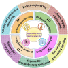
Scheme 1
Scheme 1
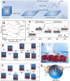
Recent major regulation strategies of Bi-based photoelectrocatalysts, which can be typically divided into six categories: defect engineering, atomic doping engineering, organic framework engineering, inorganic heterojunction engineering, crystal face engineering, and alloying and polarization engineering
Fig. 1
Fig. 1
Regulation mechanism of atomic Bi vacancy on the activity and reaction path of CO2RR. a Schematic diagram of upshifting Fermi level by forming atom vacancies in Bi catalyst to decrease the CO2RR overpotentials. The dot-dash line represents the interface between Bi electrode and electrolyte; b free energy for *OCHO generation on ideal and defective Bi (001) surfaces [71]; © 2020 Elsevier B.V. c A schematic illustration for synthetic procedure of bimetallic Cu–Bi nanostructures; d charge density of bimetallic Cu–Bi. The yellow area represents the accumulation of electrons, and the cyan area represents the reduction of electrons; e Gibbs free energy profiles of formate production pathways on pure Bi and bimetallic Cu–Bi [72]. © 2023 Wiley–VCH GmbH
Fig. 2
Fig. 2
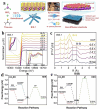
Fabrication, characterization, and reaction pathways of oxygen vacancy (Vo). a Synthesis of renewable oxygen vacancy defect single-cell BOC nanosheets by ultraviolet irradiation; b Quasi in situ XPS spectra of Bi 4f for the UV-10-BOC nanosheets.; c calculated free energy diagrams and schematic illustration of CO2 photoreduction to CO [75]. © 2021 Wiley–VCH GmbH. d, e Free energy diagrams for the reduction of CO2 to CO or *CHO over GQDs/BWO6-x and BWO; f illustration of GQDs/BWO6-x surface microstructure; g illustration of a possible mechanism for photocatalytic CO2RR of GQDs/BWO6-x [76]. © 2021 Elsevier B.V. All rights reserved
Fig. 3
Fig. 3
Other strategies of modulating the defect sites with nonmetallic elements (Cl, S, et al.). a Reaction pathway for photocatalytic CO2 reduction over Bi5O7Cl based on DFT calculation; b photocatalytic CO2 reduction mechanism promoted by light-induced Cl defects [79]. Copyright © 2022 Science China Press. c Schematic illustration of the hydroxyl trapping by VC passivate layer and ensure a smooth CO2 reduction at the defective sites [81]. Copyright © 2023, Crown. d Schematic diagram of the structural evolution from BBS to Bi nanosheets with S-modified edge defect sites [82]. Copyright © 2023 Wiley‐VCH GmbH
Fig. 4
Fig. 4
Atomic doping strategy optimizes the reaction pathways of Bi-based photoelectrocatalysts. a Schematic of reaction mechanism on ultra-thin Ag–BWO nanosheets for photoreduction of CO2 to CO; b DFT-calculated Gibbs free energy of reaction intermediate on BWO and Ag–BWO with related geometry structures for CO2 photoreduction [83]. © 2023 Elsevier B.V. c Schematic representation of the preparation of Ru1@Bi and Run@Bi catalysts; d Gibbs free energy landscapes for CO2 reduction to formate at 0 V versus RHE. The RDS is labeled with a black text [84]. © 2024 Wiley‐VCH GmbH. e Band structure alignments of BiO QDs and Co/BiO(1.0%); f calculated free energy diagrams for CO2 reduction into CO on BiO QDs and Co/BiO(1.0%) [85]. © 2023 Elsevier BV
Fig. 5
Fig. 5
Doping-induced charge reconstruction and directional evolution of reaction pathways. a Catalytic process model of Cu–BOC; b Gibbs free energy profiles of formate production pathways on BOC and Cu–BOC; c Gibbs free energies for the formation of H* on BOC and Cu–BOC [86]. © 2024 Wiley–VCH GmbH. d The charge density difference between Bi and Ti–Bi, the Bi, Ti, C, H, and O atoms were illustrated in purple, blue, brown, white, and red, respectively; e free energy diagrams for CO2RR on Bi and Ti–Bi [87]. © 2023 Wiley–VCH GmbH; f EPR profiles of Bi(Te)2/NCNSs and Bi/NCNSs [90]. Copyright © 2022, American Chemical Society
Fig. 6
Fig. 6
Structural evolution characterization and comparison of reaction energy barriers for doping catalysts. a Synthesis and reconstruction of BiS-1 nanorods catalyst; b normalized XANES and c FT-EXAFS of Bi L3-edge spectra for BiS-1 under CO2RR from OCP to -1.5 V. The in situ XANES tests are conducted in a customized three-electrode cell with CO2-filled 0.5 M KHCO3 [91]. © 2024 Wiley–VCH GmbH. Free energy diagrams of CO2RR and HER on d Bi surface and e Bi(B) surface [92]. © 2021 Wiley‐VCH GmbH
Fig. 7
Fig. 7
Co-doping strategy optimizes the electronic structure and reaction pathways. a Fabrication and reconstruction from Sn–BiOx to Vo-BOC-NS.; b Gibbs free energy of key intermediates for CO2RR to HCOOH; c Bader charge density difference; d corresponding 2D electron localization function (ELF) of the left: Bi2O2CO3 and right: Bi2O2CO3 with one oxygen vacancy. Red and blue represent higher and lower levels of electron localization, respectively [93]; © 2022 The Authors. e UV–Vis diffuse reflectance spectra and f Tauc curves of BOC and BOC-Ca-Cex (X = 1, 2, 4, 6, 8) materials [95]. © 2025 Elsevier Inc
Fig. 8
Fig. 8
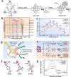
Hierarchical structure design and mechanism of photoelectrocatalytic CO2RR with COF hybrid materials. a Schematic illustration of the preparation of HBWO@Br-COFs hybrid materials. SEM images of b HBWO and c HBWO@Br-COF-2; d electron transfer pathway and CO2 reduction mechanism [100]; © 2023 Elsevier B.V. e Enhanced photocatalytic CO2RR mechanism of Bi2O2S@TpPa-2-COF heterojunction [101]. © 2023 Elsevier B.V. Top view of optimized single hydrogen adsorption configuration of f COF-TaTp, and g 5% Bi/COF-TaTp. h Free energy diagram for hydrogen evolution of COF-TaTp and 5% Bi/COF-TaTp [102]. © 2022 Wiley‐VCH GmbH
Fig. 9
Fig. 9
Multidimensional structural engineering of Bi-based COF heterojunctions and the cross-scale charge transport mechanism jointly regulate CO2RR. a Schematic illustration for the preparation of Br-COFs@BiOCl composites; b schematic illustration of the relative band positions and charge transfer process before contact, after contact and under light irradiation [103]; © 2025 Elsevier B.V. c Preparation process for the core–shell Bi2MoO6@COF composites; d proposed mechanism of photocatalytic CO2 reduction for Z-scheme Bi2MoO6@COF heterojunction [104]; © 2025 Elsevier B.V. e Schematic diagram of synthesis of Bi@COF-316; f schematic depiction of natural and artificial photosynthesis; g schematic diagram of the photocatalytic CO2 reduction and H2O oxidation mechanism. [105]. © 2025 Elsevier B.V
Fig. 10
Fig. 10
Structural evolution and catalytic mechanisms of Bi-MOFs. a Schematic illustration of metal–organic cube, linkage, and ACO topology from inorganic zeolites to ZMOFs, and Bi-ZMOFs; b free energy diagrams for HCOOH formation on the Bi of PZH-1 (red) and PZH-2 (blue) system, respectively. [110]; © 2023 Wiley‐VCH GmbH. c Simulated cluster representing Bi-MOF catalytic sites. Blue arrows show the binding sites of adsorbates; d free energy diagram of HER and HCOOH formation. The ~ energy value indicates the average energy of the three binding sites; e suggested reaction pathway. Each arrow indicates a reaction with an addition of an electron. *COOH, an intermediate for CO formation, does not bind [111]. © 2020 Elsevier B.V
Fig. 11
Fig. 11
Interfacial engineering and reaction mechanisms in Bi-MOF hybrid systems. a Proposed mechanism for the improved CO2 reduction activity with Bi/UiO-66-Zr-MOF structure. In the schematic, (1) ~ (4) correspond to the chemical reactions of Zr6O4(OH)4(BDC)6 + 18HCO3 → 3[Zr2(OH)2(CO3)4]2− + 8 H2O + 6CO2 + 6BDC2−, CO2 + OH ↔ HCO3, HCOOH ↔ H+  + HCOO and 2CO32− + 4 H+  → 2CO2 + 2H2O, respectively [112]; © 2023 Elsevier B.V. b Schematic illustration of the Cs3Bi2Br9/Bi-MOF composite. Electrostatic potential diagrams for c Cs3Bi2Br9 and d Bi-MOF; e diagrams of the relative band edge positions of Cs3Bi2Br9 and Bi-MOF [113]. Copyright © 2023, American Chemical Society
Fig. 12
Fig. 12
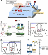
Multipathway regulatory mechanism of photoelectrocatalytic CO2RR of Bi-based MOFs with specific ligand structure. a Schematic presentation of chemical transformation of Zr-DMBD to BiNP@Zr-DMBD; [114] © The Royal Society of Chemistry 2025. b In situ FT-IR spectra of SC-Bi-PMOF-6 h under light irradiation after purging with CO2 and H2O vapor; c Gibbs free energy change (ΔG) and reaction pathways for photocatalytic CO2 reduction to CO and CH4 over Bi-PMOFs; d schematic of photocatalytic CO2 reduction on SC-Bi-PMOFs; e schematic illustration of the preparation procedure of Bi-MOFs; [115] © 2024 Elsevier B.V. All rights reserved. f Bader charge analyses of Bi–BDC, Bi–BTC, and Bi–PMA; g Gibbs free energy diagram for ECR to HCOOH process on Bi–BDC, Bi–BTC, and Bi–PMA. [116]. Copyright © 2025, American Chemical Society
Fig. 13
Fig. 13
Heterogeneous interface engineering of Bi-based materials and inorganic semiconductors. a Schematic representation of the crystal structure and metal coordination of Bi2WO6 and TiO2 in BiW/Ti hybrids; b charge transfer mechanism in Bi2WO6/TiO2 heterojunctions [121]; © 2022 The Authors. Published by Elsevier B.V. Gibbs free energy diagrams for c CO2 reduction to C2H4 on the In–SV–Bi2S3 surface and d CO2 reduction to CO on pristine Bi2S3 and In2S3 surfaces; e configurations of two *CO adsorbed on Bi2S3 and In2S3 surfaces [122]; Copyright © 2023, American Chemical Society. f Schematic illustration of BiVO4/Bi2S3 heterojunction: the charge transfer and separation inducted by the internal electric field, and the formation of the direct Z-scheme heterojunction under visible light irradiation; g schematic illustration of the photocatalytic CO2 reduction process (Note: B/B and M/B/B refer to BiVO4/Bi2S3 and MnOx/BiVO4/Bi2S3, respectively [123]. © 2022 Elsevier Ltd
Fig. 14
Fig. 14
Design and mechanistic elucidation of Bi-based heterojunctions. a Schematic synthesis process of the composite Bi2O2.33-CdS photocatalyst; b schematic illustration of Bi2O2.33-CdS heterojunction charge transfer mechanism [130]; © 2022 Published by Elsevier Ltd on behalf of the editorial office of Journal of Materials Science & Technology. c Proposed mechanism for CO2 photoreduction catalyzed by Bi2S3/ZnCdS; d free energy required for photoreduction of CO2 to CO of ZnCdS and Bi2S3/ZnCdS [131]; © 2022 Chongqing University. Production and hosting by Elsevier B.V. on behalf of KeAi. e Schematic illustration for the preparation and CO2 photoreduction process of the Bi19S27Br3/g-C3N4-5 composite; f DFT calculations of adsorption energies for Bi19S27Br3, g-C3N4, and Bi19S27Br3/g-C3N4 composite [132]. © 2022 Elsevier B.V
Fig. 15
Fig. 15
Crystallographic facet engineering and in situ phase evolution in Bi-based electrocatalysts. DFT studies of Bi5O7NO3 crystallographic facets: a Crystal plane model of (141) and (080) facets. Bi: purple; O: red; N: blue; H: white; b, c oxygen vacancy models on (141) and {080} facets; d, e adsorption models of NH4+ adsorbed on (141) and (080) facets of Bi5O7NO3; f schematic illustration of possible carrier transfer path between (141) and (080)-OV facets [136]; © 2024 Wiley‐VCH GmbH. g Scheme of phase transition from initial NaBiS2 nanodots to final Bi (110)-S-Na nanosheets under in situ CO2 electroreduction at -1 A‧cm−2. Energy diagrams of h formate and i H2 pathway on these three models [137]. © 2023 Elsevier Inc
Fig. 16
Fig. 16
Surface engineering of Bi-based catalysts and dynamic phase transformation synergistically regulate the electroreduction of CO2 to formic acid. a PDOS of the O atoms for *OCHO intermediate and Bi atoms of the adsorption sites for different Bi surfaces; b free energy diagrams of formate formation by eCO2RR on different Bi surfaces; c free energy diagrams of HER on different Bi surfaces [138]; © 2021 Wiley‐VCH GmbH. Potential-dependent in situ XRD patterns of d Se–Bi and e Bi in CO2-saturated 0.5 M KHCO3 solution measured under synchrotron radiation at 0.6333 Å; f diffraction intensities of the Bi (104) and Bi (012) facets in the Se–Bi and Bi catalysts as a function of the applied potential in CO2-saturated 0.5 M KHCO3 solution [139]; © 2025 Wiley‐VCH GmbH. g, h Comparison of FE and production rate of HCOOH in BiOBr, BiOI and BiOCl. Error bars were obtained by measuring the liquid products in triplicate, and the center value for the error bars is the average of the three independent measurements; i corresponding partial current density in CO2-saturated 1 M KHCO3 electrolyte solution using a GDE flow cell; j-l potential-dependent in situ XRD patterns of BiOBr (j), BiOI (k) and BiOCl (l) in CO2-saturated 0.1 M KHCO3 solution, plotted in arbitrary units (a.u.) versus diffraction angle 2θ [140]. Copyright © 2023, The Author(s)
Fig. 17
Fig. 17
Synergizing alloy synthesis and ferroelectric polarization for efficient CO2-to-formate electroreduction. a Schematic synthetic procedure for Pd3Bi IMA and Pd3Bi SSA; b energetic trend of CO2RR to formic acid on Pd3Bi IMA, Pd3Bi SSA and pure Pd [144]; © 2021 Wiley‐VCH GmbH. c Schematic illustration for the formation of surface oxygen vacancies on Bi3TiNbO9. Blue, gold, and purple spheres represent Ti/Nb, Bi and O atoms, respectively. d COMSOL simulation of polarization-induced electric field on Bi3NbTiO9 sheets: un-poled, intermediate poled, fully poled. The red arrow represents the polarization direction of a single domain [151]. Copyright © 2021, The Author(s)
Fig. 18
Fig. 18
CO2RR regulation mechanism by Bi-based bimetallic interface engineering. a Scheme of CO2RR on Sn–Bi bimetallic interface. Gibbs free energy profiles of CO and HCOOH production pathways on b Sn–Bi alloy surface and c Sn–Bi bimetallic interface [152]; Copyright © 2022, The Author(s) The calculated Gibbs free energy diagrams for d CO2-to-HCOOH conversion and e CO2-to-CO conversion on the Sb site of Sb and Sb6Bi2 slabs. The gold, purple, red, white and brown spheres represent Sb, Bi, O, H and C atoms, respectively; f difference in limiting potentials for CO2 reduction and H2 evolution [154]; © 2022 Elsevier B.V. All rights reserved. g Proposed mechanism for CO2 conversion to formate using Bi–Pb electrodes. Calculated Gibbs free energy profiles for h formic acid generation and i H2 formation on Bi85Pb15, Bi60Pb40 and Bi50Pb0 [155]. © The Royal Society of Chemistry 2025
Fig. 19
Fig. 19
Insights into the dynamic structure evolution and formation mechanism of Bi-based catalysts by SAXS/XRD/XAFS combining technique. a Schematic map of the SAXS/XRD/XAFS combined setup [156]; b-e in situ SAXS, XRD, and XAFS data collected by the newly developed SAXS/XRD/XAFS combined technique under isothermal isobaric conditions of 423 K and 3 MPa [159]; Copyright © 2024, Science China Press. f Schematic illustration of the formation mechanism for the PVP-capped Bi nanospheres (PVP@Bi-NSs) electrocatalyst [160]. © 2024 Elsevier B.V
Fig. 20
Fig. 20
In situ multiscale investigation of activation pathways and uncovering the CO2RR mechanism. a Electrocatalyst morphology and performance variations after CO2 reduction and multiscale in situ X-ray scattering methodology; b time-resolved X-ray scattering during the catalyst activation and initial CO2RR stage. [161] Copyright © 2025, The Author(s)

Similar articles

References

    1. X. Li, S. Wang, L. Li, Y. Sun, Y. Xie, Progress and perspective for in situ studies of CO2 reduction. J. Am. Chem. Soc. 142(21), 9567–9581 (2020). 10.1021/jacs.0c02973 - PubMed
    1. J. Fu, K. Jiang, X. Qiu, J. Yu, M. Liu, Product selectivity of photocatalytic CO2 reduction reactions. Mater. Today 32, 222–243 (2020). 10.1016/j.mattod.2019.06.009
    1. X. Li, W. Bi, M. Chen, Y. Sun, H. Ju et al., Exclusive Ni-N4 sites realize near-unity CO selectivity for electrochemical CO2 reduction. J. Am. Chem. Soc. 139(42), 14889–14892 (2017). 10.1021/jacs.7b09074 - PubMed
    1. X. Shen, Q. Meng, M. Dong, J. Xiang, S. Li et al., Low-temperature reverse water–gas shift process and transformation of renewable carbon resources to value-added chemicals. Chemsuschem 12(23), 5149–5156 (2019). 10.1002/cssc.201902404 - PubMed
    1. D. Cui, W. Hao, J. Chen, The synergistic effect of heteroatom doping and vacancy on the reduction of CO2 by photocatalysts. ChemNanoMat 7(8), 894–901 (2021). 10.1002/cnma.202100148

LinkOut - more resources