Review
. 2025 Jul 31:53:656-703.
doi: 10.1016/j.bioactmat.2025.07.035. eCollection 2025 Nov.

Advancements in biomaterials and bioactive solutions for lumbar spine fusion cages: Current trends and future perspectives

Affiliations
Review

Advancements in biomaterials and bioactive solutions for lumbar spine fusion cages: Current trends and future perspectives

Iulian Antoniac et al. Bioact Mater. .

Abstract

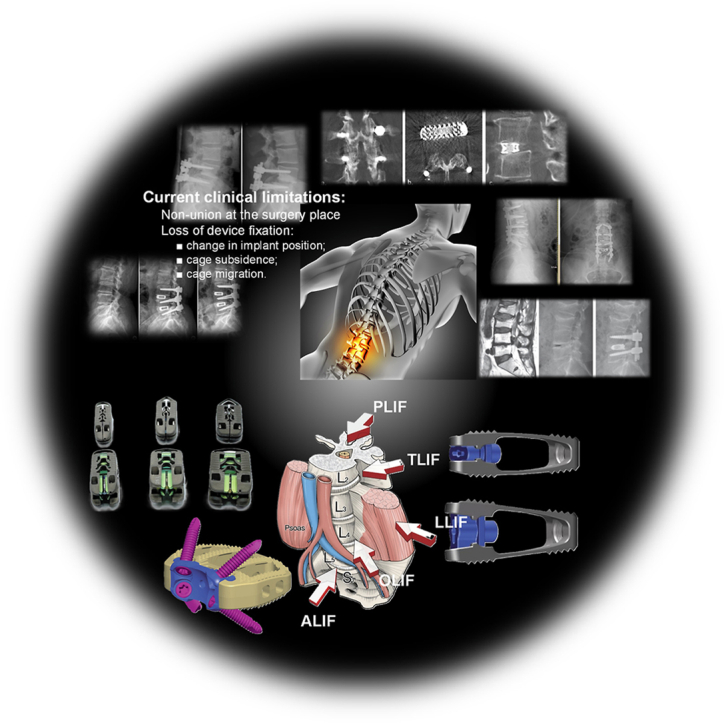
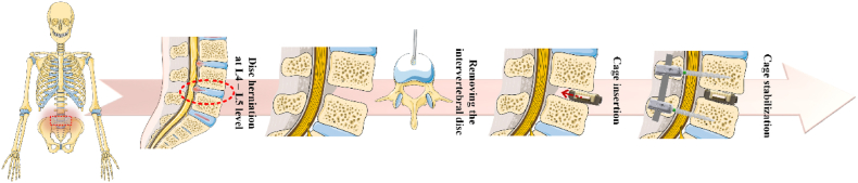
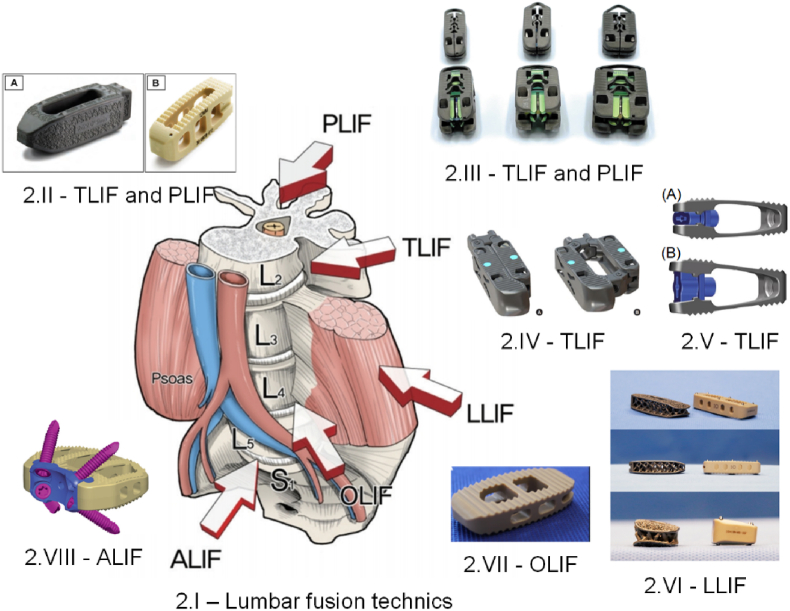
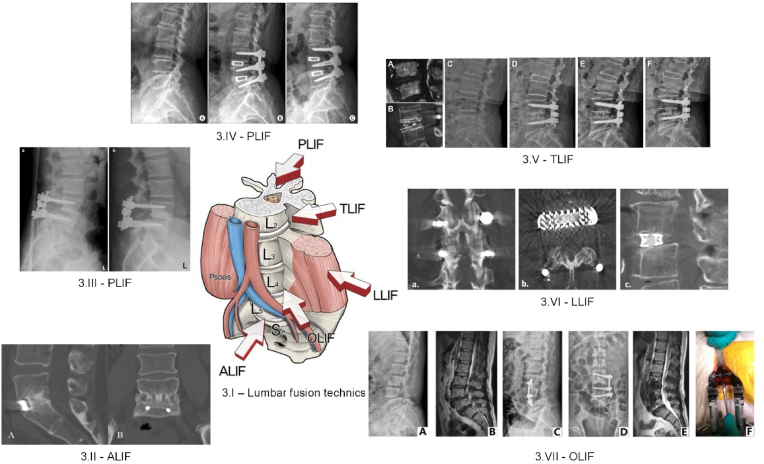
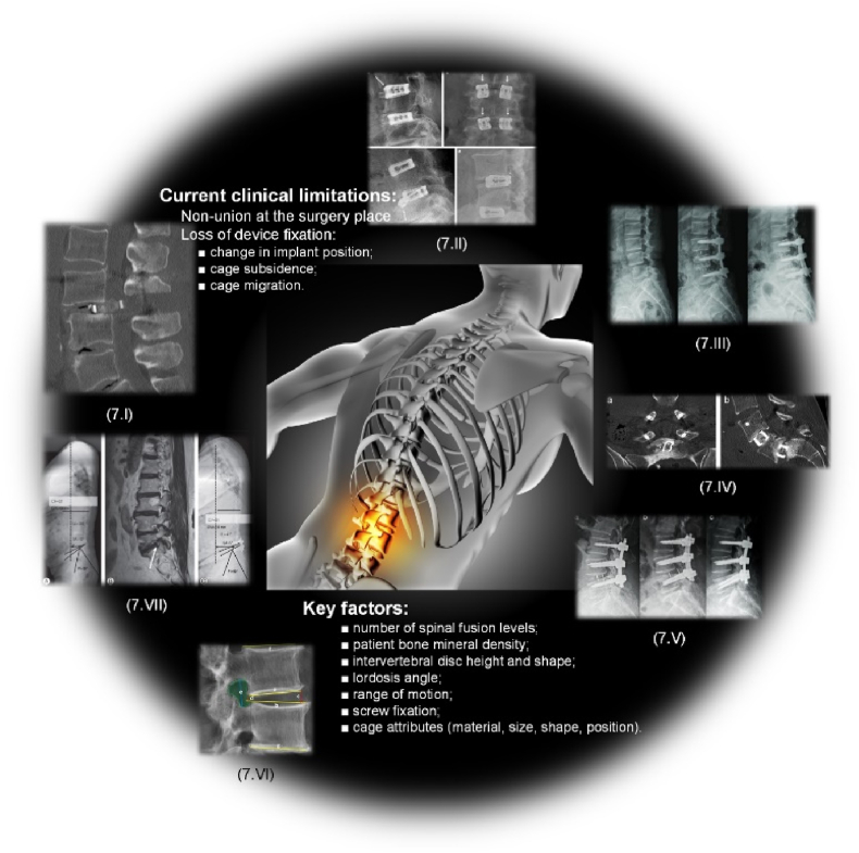
Spinal fusion is considered today as the last treatment option for different spinal conditions, such as degenerative and infectious illnesses. It consists of fusing two or more vertebrae to obtain reinforcement/fixation based on several methods used to sustain osteosynthesis and grafting, such as cage insertion in the intervertebral space, which provides an important level of mechanical stability, impacting only a low amount of the natural biomechanics of the spine and facilitating the implant bony ingrowth. This review paper first explores the background of intervertebral fusion, emphasizing medical applications and material properties of interbody fusion cages. It then provides a brief historical overview and discusses antibacterial efficacy-related issues. Additionally, some of the most met-in-clinical practice lumbar interbody cages with a detailed description of their geometry and examples of clinical trials performed worldwide are provided. The biomaterials used in lumbar cage manufacture are comprehensively described. In the last part of this review paper, special attention is devoted to prospective biomaterials and coatings for spine fusion cages. Firstly, the rationale for using Mg-based alloys or high osteogenic polycaprolactone as biodegradable and bioresorbable alternatives in the spinal cage industry, addressing the clinical limitations of traditional Ti alloys and polyether ether ketone, is provided. Then, a more conservative approach, focusing on the use of bioactive or antibacterial coatings on the already certified biomaterials, is presented as a second alternative to the existing products on the market. Relevant literature studies are reviewed, and the osteointegrative, bioactive, or antibacterial character of the coatings is explained. Finally, our review identifies current clinical limitations and offers future perspectives that will provide better bioactive solutions, improving the existing biomaterials.

Keywords: Bioactive solutions; Biodegradable cages; Clinical trials; High osteogenic polycaprolactone; Mg-based alloys; Spinal fusion.


Conflict of interest statement

Julietta V. Rau is an associate editor board member for Bioactive Materials and was not involved in the editorial review or the decision to publish this article. Iulian Antoniac is an editorial board member for Bioactive Materials and was not involved in the editorial review or the decision to publish this article. All authors declare that there are no competing interests.

Figures

Image 1
Graphical abstract
Fig. 1
Fig. 1
Exemplification of anterior lumbar interbody fusion surgical procedure consisting of an intervertebral cage insertion between spinal levels. This Figure was generated using images assembled from Servier Medical Art, which are licensed under CC BY 4.0 (https://smart.servier.com, accessed on January 23, 2025).
Fig. 2
Fig. 2
Examples of commercial fusion cages associated with different surgical interventions. (2.I) Main lumbar interbody fusion surgical approaches [48] (Figure is licensed under CC BY-NC 4.0); (2.II) CTL Amedica, Dallas, TX, USA fusion cages: (A) TLIF Si3N4 Valeo™ OL, (B) PLIF PEEK Phantom™ [52] (Figure is licensed under CC BY-NC-ND 4.0); (2.III) Acellus, Palm Beach Gardens, FL, USA TiHawk7, TiHawk9, and TiHawk11 (from left to right) [96] (Figure is licensed under CC BY-NC-ND 4.0); (2.IV) Amplify Surgical, Inc., Irvine, CA, USA Dual-X TLIF cage [97] (Figure is licensed under CC BY-NC 4.0); (2.V) Signus Medizintechnik GmbH, Alzenau, Germany TLIF Vertaconnect [98] (Figure is licensed under CC BY 4.0); (2.VI) NuVasive, Globus Medical, San Diego, CA, USA 3D Ti Modulus and CoRoent XL PEEK [99] (Figure is licensed under CC BY 4.0); (2.VII) Sanatmetal, Eger, Hungary OLIF PEEK EMERALD™ cage [53] (Figure is licensed under CC BY 4.0); (VIII) DePuy Synthes Spine, PA, USA PEEK SynFix® stand-alone cage [54] (Figure is licensed under CC BY 4.0).
Fig. 3
Fig. 3
Medical images associated with different surgical interventions.(3.I) Main lumbar interbody fusion surgical approaches [48] (Figure is licensed under CC BY-NC 4.0); (3.II) CT scan image confirming a successful grade I fusion: (A) sagittal image, (B) coronal image based on ALIF insertion of DePuy Synthes Spine, PA, USA PEEK SynFix® stand-alone cage [122] (Reprinted from Ref. [122] Copyright (2025), with permission from Elsevier); (3.III) X-ray images of a young patient after a PLIF surgery using a Medtronic Sofamor Danek, Memphis, TN, USA PLDLLA Hydrosob™ taken (a) at 1 day post-surgery, and (b) after 1 year post-surgery [145] (Figure is licensed under CC BY-NC 2.0); (3.IV) Medical images of a patient with spinal stenosis taken before and after PLIF surgery based on Stryker, NJ, USA Titanium O.I.C® cage: (A) preoperative X-ray image evidencing a reduced disc height, (B) lateral view immediately after surgical procedure, (C) lateral view after 3 year post-surgery (Figure is licensed under CC BY 2.0) [140]; (3.V) Medical images of a patient with L4-L5 disc herniation that underwent TLIF surgery with Medtronic, Memphis, Tennessee, USA PEEK Capstone cage: (A) MRI image before surgery, (B) 1 year image evidenced solid fusion and cage subsidence, (C) preoperative upright medical image, (D) reconstruction after TLIF surgery, (E) 1 year image showing loss of disc height and segmental lordosis due to cage subsidence, (F) X-ray image at 33 months post-surgery [119] (Reprinted from Ref. [119] Copyright (2025), with permission from Elsevier); (3.VI) CT scan images presenting different views of a strong fusion (a) coronal view, (b) axial view, (c) sagittal view based on Nuvasive, San Diego, CA, USA Titanium XLIF Modulus cage [106] (Figure is licensed under CC BY 4.0); (3.VII) Medical images of a patient exhibiting grade I spondylolisthesis at L4-L5 level and disc herniation at L3-L4 level treated with Medtronic, Mineapolis, MN, USA Clydesdale Spinal System: (A) and (B) preoperative X-ray and MRI images, (C) anterior-posterior, (D) lateral X-ray and (E) sagittal MRI postoperative images, (F) intraoperative image [124] (Reprinted from Ref. [124] Copyright (2025), with permission from Elsevier).
Fig. 4
Fig. 4
Mechanical and biological investigations obtained for: Ti-alloy spinal cages – (4.I) Von Mises stress map obtained in accordance with ASTM F2267-04 standard for a 500 N axial compression load: (A)÷(C) generic device, (D)÷(F) patient anatomy adapted-device; (4.II) Intraoperative images taken for a 34-year old man: (A) discectomy, (B) implant preparation with allograft material, (C) implant insertion, (D) X-ray scan [167] (Reprinted from Ref. [167] Copyright (2025), with permission from Elsevier); PEEK and PEEK – Ti coated cages – (4.III) Average dorso-ventral stiffness at two different frequencies, (4.IV) interoperative images for merino sheep lumbar fusion model: (A) PEEK-Ti and (B) PEEK cages with autologous bone graft, (C) discectomy, (D) surgical placement, (E) cage implantation [175] (Reprinted from Ref. [175] Copyright (2025), with permission from Elsevier); Si3N4cages – (4.V) Comparison of mean subsidence as a function of loading cycles in the case of (A) low density and (B) high density foam substrate for Si3N4, PEEK, and Ti4Al4V cages [184] (Figure is licensed under CC BY-NC-ND 4.0), (4.VI) Histological sagittal analysis of the inside and outside of PEEK (a) ÷ (h) and Si3N4 (i) ÷ (p) cages in the case of caprine lumbar fusion model [185] (Reprinted from Ref. [185] Copyright (2025), with permission from John Wiley and Sons); Uncalcined hydroxyapatite/poly L-Lactide (F-u-HA/PLLA) cage – (4.VII) ROM of different surgical sheep groups: (A) flexion-extension, (B) lateral bending (loading ± 6 Nm) (Intact – no implant, AIB – corticocancellous grafts, carbon fiber cage (CFC) – Brandigan I/F cage, DePuy Acromed. Inc., Raynaham, MA, USA, F-u-HA/PLAA – high osteogenic cage); (4.VIII) Histologic interface between high osteogenic (A), and CFC (B) cages, and natural bone [231] (Reprinted from Ref. [231] Copyright (2025), with permission from Elsevier).
Fig. 5
Fig. 5
High osteogenic potential lumbar cages: Mg-Zn-Nd-Zr – (5.I) Corrosion surface analysis after 28 days immersion in Hank's solution with an adjusted pH of 7.4 and EDS spectra for bare and MAO-coated Mg-alloy samples: (a) surface morphology and elemental composition, (b) cross-section morphology and EDS analysis; (5.II) RT-qPCR osteogenic differentiation genes (BMP2 – bone morphogenetic protein 2, OPG – osteoprotegerin, RUX2 – runt-related-transcription factor 2, COL-I – collagen I): (a) 7 days, (b) 14 days (statistical significance ∗ p < 0.05, ∗∗p < 0.01) [257] (Figure is licensed under CC BY-NC-ND 4.0); Poly (epsilon-caprolactone) with 20 % beta-tricalcium phosphate (mPCL-TCP) – (5.III) μ-CT images in a pig lumbar fusion model: (A)/(B) cage (scaffold + rhBMP-2) and (C)/(D) autograft bone at 3/6 months post-surgery, respectively, (E) Bone volume per tissue volume (BV/TV) ratio (∗p < 0.05); (5.IV) Typical variations of ROM construct rigidity at (A) 3 months, (B) 6 months, and (C) limitation of ROM (∗p < 0.05) [258] (Reprinted from Ref. [258] Copyright (2025), with permission from Elsevier).
Fig. 6
Fig. 6
In vitro and in vivo analysis results obtained in the case of different lumbar cages with surface treatment or coatings. Sun et al., 2024 [346]: (6.I) In vitro results on hBMSCs: (a) Life/Dead assay, (b) CCK-8 assay, (c) CLSM images of cell cytoskeleton, (d) ALP activity; (6.II) In vivo results: (a) 2D and 3D μ-CT images, (b) quantitative analysis for new bone formation (BV/TV and Tb.Th), (c) intervertebral fusion status analysis (size bar = 1 mm) (Figure is licensed under CC BY-NC 3.0); Wu et al., 2023 [359]: (6.III) (a)/(b) Surface morphology/Contact angle values: (a-1)/(b-1) 800 °C, (a-2)/(b-2) 800 °C and SB, (a-3)/(b-3) 800 °C, acid-etching, and alkali-etching after SB (AAS); (6.IV) In vitro tests: (a) MC3T3-E1 culture on Day 1 (a-1) and Day 5 (a-2), (b) osteogenic ALP (b-1) and mineralized ARS (b-2) (∗p < 0.05, ∗∗p < 0.01, ∗∗∗p < 0.001) (Reprinted from Ref. [359] Copyright (2025), with permission from Elsevier); Kodama et al., 2021 [349]: (6.V) Antibacterial in vitro test: (A) Agar plates showing inhibition zone, (B) Size of bacteria inhibition zone, (C) Colonies on agar plates, (D) Number of colonies ∗∗p < 0.01, (E) Crystal violet staining at 24 and 48 h, (F) Spectrometer data (average ± standard deviation, n = 3, ∗p < 0.05 T-test (scale bars = 1 mm); (6.VI) In vivo test: Wound image and μ-CT evaluation: (A) Surgical images, (B) Wound scoring, (C) μ-CT image of Ti cage, (D) μ-CT image of Ti-HACC cage, (E) CT score (average ± standard deviation, n = 6 - Ti cage and n = 7 – Ti-HACC, ∗p < 0.05 Mann-Whitney U test (scale bars = 0.5 mm) (Reprinted from Ref. [349] Copyright (2025), with permission from Elsevier); Ishihama et al., 2021 [357]: (6.VII) Antibacterial in vitro test: (A) High bacterial bioluminescent signals for PEEK cage and absence of bacterial signals for PEEK-Ag+, (B) Bacterial photon intensity (p = 0.0032), (C) SEM images indicated the presence of S. aureus and biofilm existence – PEEK cage, (D) SEM images with no pathogens – PEEK-Ag+ cage; (6.VIII) Histopathology results: (A) PEEK cage – large abscess presence (∗), (B) - PEEK-Ag+ cage, (C) PEEK – cage with enlarged images (D) and (E) revealing bacterial clots and inflammatory cells (bars: A,B – 2000 μm, C – 1000 μm, D – 400 μm, E − 200 μm (Figure is licensed under CC BY-4.0); Shimizu et al., 2017 [360]: (6.IX) In vivo test: (A) μ-CT images: (a), (b) uncoated PEEK cage, (c), (d) TiO2-coated PEEK cage, (B) Bony union rate; (6.X) In vivo results: (A) Histology: (a) uncoated PEEK cage, (b) TiO2-coated PEEK cage, (c) magnified image, (B) Histomorphometry measurement of bone-implant contact ratio (Figure is licensed under CC BY-4.0).
Fig. 7
Fig. 7
Current clinical limitations and key factors in lumbar fusion surgery: (7.I) Example of cage migration: CT scan image showing displacement and cage position modification generating central canal stenosis [386] (Figure is licensed under CC BY-3.0); (7.II) Example of cage subsidence: (a) lateral view, (b) anterior-posterior view exhibiting pseudoarthrosis, (c) lateral view presenting cage breakage, (d) lateral view evidencing cage retropulsion [388] (Figure is licensed under CC BY-4.0); (7.III) Example of cage subsidence and influence of spinal fusion level number after OLIF: (a) pre-operatory image for OLIF at L3-L4-L5 levels, (b) postoperative image taken immediately after surgical intervention, (c) 6 months post-surgery image showing an important cage subsidence [48] (Figure is licensed under CC BY-NC 4.0); (7.IV) Example of CT scan presenting non-union at L5-S1 level at 1 year post-surgery: (a) coronal view, (b) sagittal view [166] (Figure is licensed under CC BY-NC-ND 4.0); (7.V) Example of migration cage and pedicle screw loosening influence: (a) lateral view of L4-L5 TLIF and L3-L5 bilateral posterior instrumentation, (b) PCM at L4-L5 level at 13 days post-operatively, (3) lateral view at 2 days after revision surgery (cage was removed and the right pedicle screw at L5 was improved [387] (Figure is licensed under CC BY-4.0); (7.VI) Example of measurements on plan radiograph [397] (Figure is licensed under CC BY-NC-ND 4.0); (7.VII) Example of aggravation of sagittal balance after PLIF at L5-S1 level with 8° lordotic cage: (A) preoperative image, (B) MRI image presenting stenosis at L5-S1 (white arrow), (S) Sagittal parameters did not improve even after 2 years post-surgery [398] (Figure is licensed under CC BY-NC-4.0). Fig. 7 was generated using an image from www.freepik.com, accessed on February 3, 2025.

Similar articles

References

    1. Chong E., Mobbs R.J., Pelletier M.H., Walsh W.R. Titanium/polyetheretherketone cages for cervical arthrodesis with degenerative and traumatic pathologies: early clinical outcomes and fusion rates. Orthop. Surg. 2016;8:19–26. doi: 10.1111/os.12221. - DOI - PMC - PubMed
    1. Lim K.-M., Park T.-H., Lee S.-J., Park S.-J. Design and biomechanical verification of additive manufactured composite spinal cage composed of porous titanium cover and PEEK body. Appl. Sci. 2019;9:4258. doi: 10.3390/app9204258. - DOI
    1. Warren J.M., Hey L.A., Mazzoleni A.P. A finite element study of the relationship between upper body weight and the loads experienced by the human Lumbosacral spine, and fusion instrumentation, in a standing upright posture. Biomed. Eng. Adv. 2021;2 doi: 10.1016/j.bea.2021.100023. - DOI
    1. Parenteau C.S., Lau E.C., Campbell I.C., Courtney A. Prevalence of spine degeneration diagnosis by type, age, gender, and obesity using medicare data. Sci. Rep. 2021;11:5389. doi: 10.1038/s41598-021-84724-6. - DOI - PMC - PubMed
    1. Brinjikji W., Luetmer P.H., Comstock B., Bresnahan B.W., Chen L.E., Deyo R.A., Halabi S., Turner J.A., Avins A.L., James K., et al. Systematic literature review of imaging features of spinal degeneration in asymptomatic populations. AJNR Am J. Neuroradiol. 2015;36:811–816. doi: 10.3174/ajnr.A4173. - DOI - PMC - PubMed

LinkOut - more resources