. 2025 Jul 28;30(15):3151.
doi: 10.3390/molecules30153151.

Cathodic Exfoliation of Various Graphite Materials in Potassium Chloride Electrolyte

Affiliations

Cathodic Exfoliation of Various Graphite Materials in Potassium Chloride Electrolyte

Md Habibullah Dalal et al. Molecules. .

Abstract

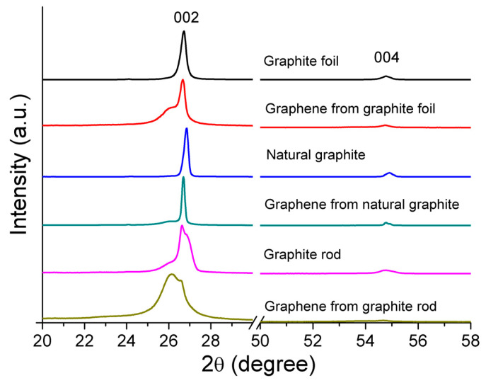
Cathodic exfoliation of graphite has emerged as an attractive method to synthesize high-quality and lo- defect graphene. Here, it is demonstrated that the type of starting graphite material influences the properties of exfoliated graphene. Graphite foil, natural graphite, and graphite rods were examined in the exfoliation processes performed in 3.0 M KCl at -15 V. The use of a graphite foil facilitates the rapid cathodic exfoliation process in comparison with structurally more compact natural graphite and graphite rods. For the graphite foil, the cathodically exfoliated graphene exhibits a low defect density (ID/IG of 0.09, a C/O ratio of 35) with graphite exfoliation yield of 92.8%. In contrast, the exfoliated graphene from natural graphite exhibits an ID/IG of 0.15, a C/O ratio of 28, and a graphite exfoliation yield of 30.5%, whereas graphene from graphite rod exhibits an ID/IG of 0.86, a C/O ratio of 30, and a graphite exfoliation yield of 19.5%. The dense structure of natural graphite and graphite rods led to longer exfoliation times. Exfoliation of graphite rods produced few-layer graphene with the smallest sheet size, whereas natural graphite and graphite foil yielded multilayer graphene with larger sheets. This study demonstrates the feasibility of using aqueous-based cathodic exfoliation to produce graphene from various graphite sources, leading to variations in sheet thickness, size, defect density, and solvent dispersibility.

Keywords: cathodic exfoliation; degree of graphitization; graphene; graphite sources.


Conflict of interest statement

The authors declare no conflicts of interest.

Figures

Figure 1
Figure 1
Optical photographs of graphite electrodes investigated in this study. (a) Graphite rod, natural graphite, and graphite foil; (b) natural graphite and the smaller cut pieces.
Figure 2
Figure 2
Photograph of dispersed cathodically exfoliated graphene from graphite foil (top), graphene from graphite rod (middle), and cathodic graphene from natural graphite (bottom) in DMF solution (concentration ~1 mg/mL). From left to right: immediately just after sonication, after 24 h, and after 72 h.
Figure 3
Figure 3
AFM images of the graphene samples obtained from graphite rod (a), natural graphite (b), and graphite foil (c). Line profiles within the AFM images represent the cross-sectional thickness (Z-height) of the graphene samples. The average thickness across the corresponding areas is shown next to the line profiles.
Figure 4
Figure 4
XRD patterns of the raw graphite foil, natural graphite, and graphite rod, normalized to their peak intensity at (002), and their corresponding electrochemical cathodic-exfoliated graphenes.
Figure 5
Figure 5
Raman spectra (excited by 633 nm laser) of (a) graphite rod, natural graphite, and graphite foil, and (b) graphene samples obtained from graphite rod, natural graphite, and graphite foil, In the insets, magnified 2D band range for corresponding cathodic-exfoliated graphene (lower trace) and the respective source graphite (upper trace).
Figure 6
Figure 6
TGA (top) and DTG (bottom) measurements of graphite rod, natural graphite, graphite foil, and the cathodically exfoliated graphene from these raw graphites from room temperature (25 °C) to 900 °C under N2 atmosphere.
Figure 7
Figure 7
(a) XPS survey and (b) high-resolution C 1s spectrum of cathodically exfoliated graphene from graphite rod, natural graphite, and graphite foil.

Similar articles

References

    1. Novoselov K.S., Geim A.k., Morozov S.V., Jiang D., Zhang Y., Dubonos S.V., Grigorieva I.V., Firsov A.A. Electric Field Effect in Atomically Thin Carbon Films. Science. 2004;306:666–669. doi: 10.1126/science.1102896. - DOI - PubMed
    1. Geim A.K. Graphene: Status and Prospects. Science. 2009;324:1530–1534. doi: 10.1126/science.1158877. - DOI - PubMed
    1. Allen M.J., Tung V.C., Kaner R.B. Honeycomb carbon: A review of graphene. Chem. Rev. 2010;110:132–145. doi: 10.1021/cr900070d. - DOI - PubMed
    1. Choi S.H., Yun S.J., Won Y.S., Oh C.S., Kim S.M., Kim K.K., Lee Y.H. Large-scale synthesis of graphene and other 2D materials towards industrialization. Nat. Commun. 2022;13:1484. doi: 10.1038/s41467-022-29182-y. - DOI - PMC - PubMed
    1. Low C.T.J., Walsh F.C., Chakrabarti M.H., Hashim M.A., Hussain M.A. Electrochemical Approaches to the Production of Graphene Flakes and their Potential Applications. Carbon. 2013;54:1–21. doi: 10.1016/j.carbon.2012.11.030. - DOI

LinkOut - more resources