

Quantification of the Mechanical Properties in the Human-Exoskeleton Upper Arm Interface During Overhead Work Postures in Healthy Young Adults
- PMID: 40807771
- PMCID: PMC12349243
- DOI: 10.3390/s25154605
Quantification of the Mechanical Properties in the Human-Exoskeleton Upper Arm Interface During Overhead Work Postures in Healthy Young Adults
Abstract
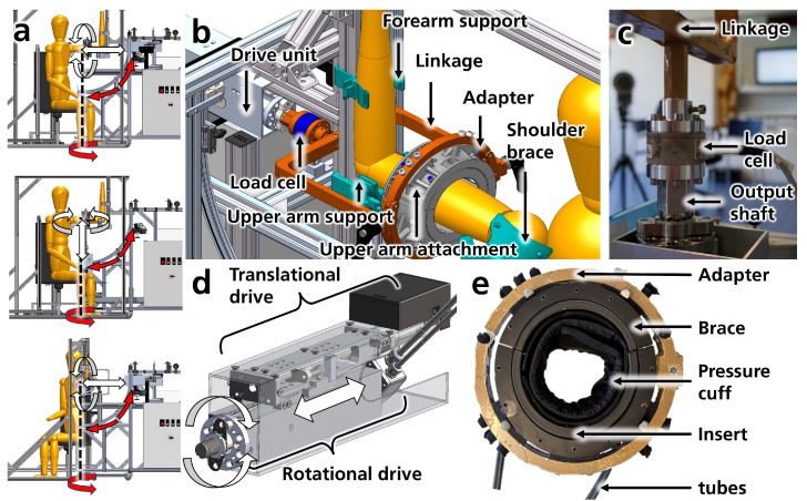
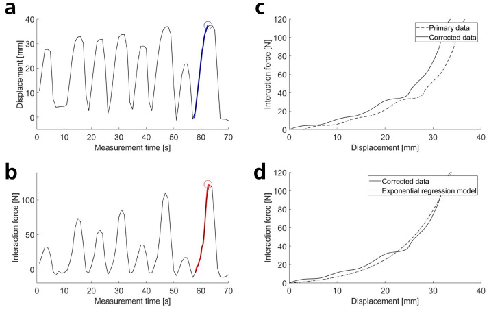
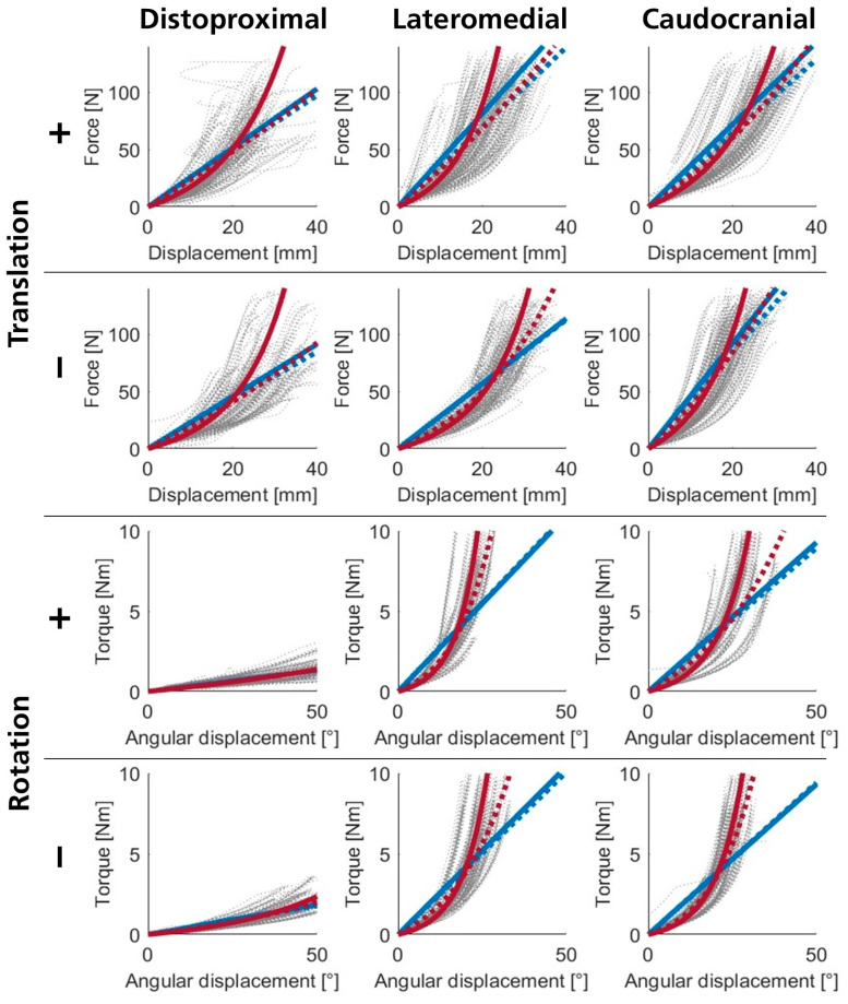
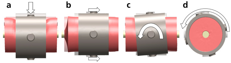
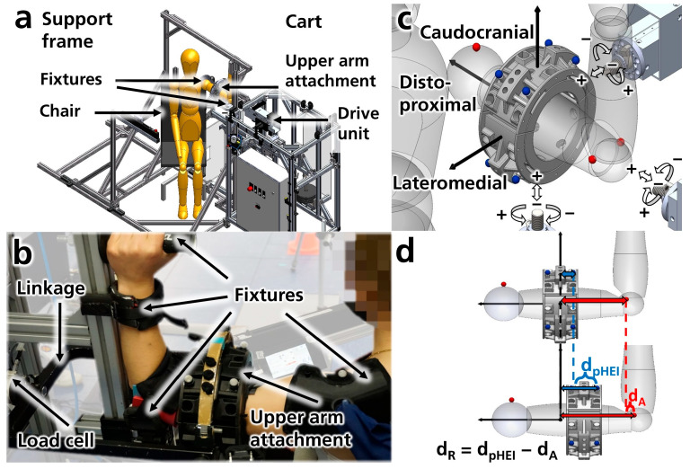
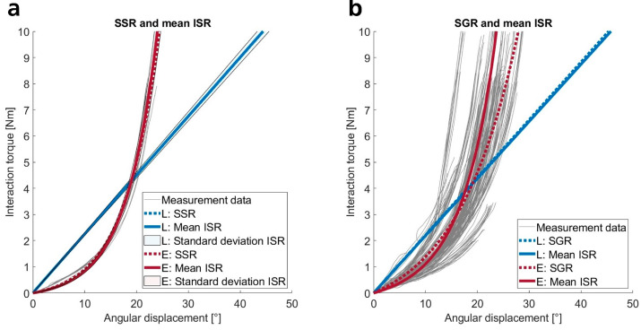
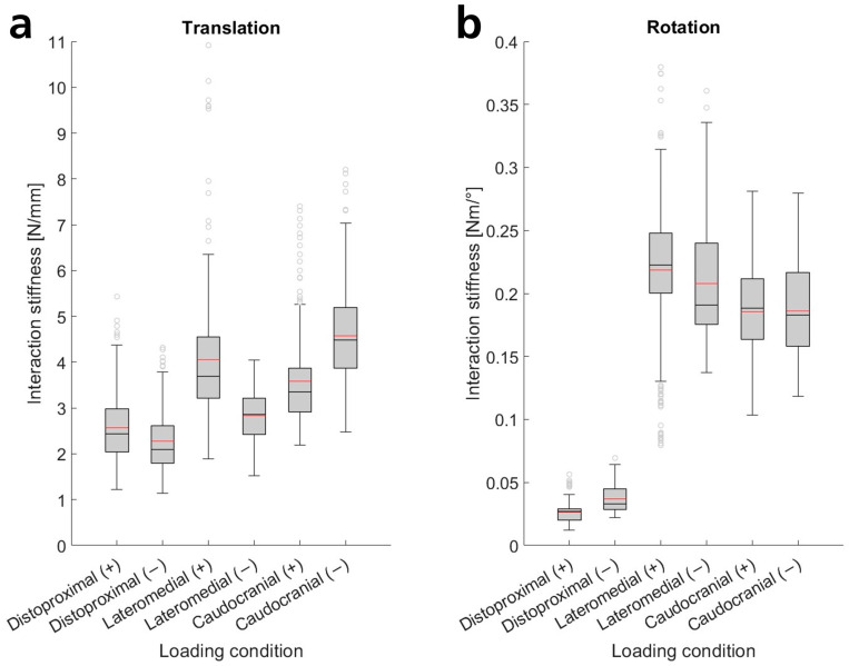
Exoskeletons transfer loads to the human body via physical human-exoskeleton interfaces (pHEI). However, the human-exoskeleton interaction remains poorly understood, and the mechanical properties of the pHEI are not well characterized. Therefore, we present a novel methodology to precisely characterize pHEI interaction stiffnesses under various loading conditions. Forces and torques were applied in three orthogonal axes to the upper arm pHEI of 21 subjects using an electromechanical apparatus. Interaction loads and displacements were measured, and stiffness data were derived as well as mathematically described using linear and non-linear regression models, yielding all the diagonal elements of the stiffness tensor. We find that the non-linear nature of pHEI stiffness is best described using exponential functions, though we also provide linear approximations for simplified modeling. We identify statistically significant differences between loading conditions and report median translational stiffnesses between 2.1 N/mm along and 4.5 N/mm perpendicular to the arm axis, as well as rotational stiffnesses of 0.2 N·m/° perpendicular to the arm, while rotations around the longitudinal axis are almost an order of magnitude smaller (0.03 N·m/°). The resulting stiffness models are suitable for use in digital human-exoskeleton models, potentially leading to more accurate estimations of biomechanical efficacy and discomfort of exoskeletons.
Keywords: exoskeleton; interaction stiffness; interface mechanics; mechanical characterization; physical human-robot interaction; physical human–exoskeleton interaction; upper arm; wearable robot.
Conflict of interest statement
The authors declare no conflicts of interest. The funders had no role in the design of the study; in the collection, analyses, or interpretation of data; in the writing of the manuscript; or in the decision to publish the results.
Figures
Similar articles
-
Passive Exoskeletons During Live Surgeries: Supporting Forward Head Postures Among Veterinary Surgeons.IISE Trans Occup Ergon Hum Factors. 2025 Jan-Mar;13(1):32-39. doi: 10.1080/24725838.2024.2411552. Epub 2024 Oct 23. IISE Trans Occup Ergon Hum Factors. 2025. PMID: 39440358
-
Effects of an exoskeleton on muscle activity in tasks requiring arm elevation: Part I - Experiments in a controlled laboratory setting.Work. 2024;77(4):1179-1188. doi: 10.3233/WOR-230217. Work. 2024. PMID: 37980590
-
Effects of an elastic hip exoskeleton on stability quantified by mechanical energetics and whole-body angular momentum during walking with treadmill belt speed perturbations.J Biomech. 2025 Jul;188:112784. doi: 10.1016/j.jbiomech.2025.112784. Epub 2025 May 27. J Biomech. 2025. PMID: 40450893
-
Side-effects and adverse events of a shoulder- and back-support exoskeleton in workers: A systematic review.Appl Ergon. 2023 Sep;111:104042. doi: 10.1016/j.apergo.2023.104042. Epub 2023 May 3. Appl Ergon. 2023. PMID: 37146320
-
Effectiveness of robotic exoskeletons for improving gait in children with cerebral palsy: A systematic review.Gait Posture. 2022 Oct;98:343-354. doi: 10.1016/j.gaitpost.2022.09.082. Epub 2022 Sep 26. Gait Posture. 2022. PMID: 36306544
References
-
- Bai S., Gurvinder S.V., Sugar T.G., editors. Wearable Exoskeleton Systems: Design, Control and Applications. Institution of Engineering & Technology; Stevenage, UK: 2018.
-
- Gull M.A., Bai S., Bak T. A Review on Design of Upper Limb Exoskeletons. Robotics. 2020;9:16. doi: 10.3390/robotics9010016. - DOI
-
- Bogue R. Robotic exoskeletons: A review of recent progress. Ind. Robot. Int. J. 2015;42:5–10. doi: 10.1108/IR-08-2014-0379. - DOI
-
- Theurel J., Desbrosses K. Occupational Exoskeletons: Overview of Their Benefits and Limitations in Preventing Work-Related Musculoskeletal Disorders. IISE Trans. Occup. Ergon. Hum. Factors. 2019;7:264–280. doi: 10.1080/24725838.2019.1638331. - DOI
MeSH terms
Grants and funding
LinkOut - more resources
Full Text Sources
Medical
