

Multi-Objective Optimization of IME-Based Acoustic Tweezers for Mitigating Node Displacements
- PMID: 40808067
- PMCID: PMC12349547
- DOI: 10.3390/polym17152018
Multi-Objective Optimization of IME-Based Acoustic Tweezers for Mitigating Node Displacements
Abstract
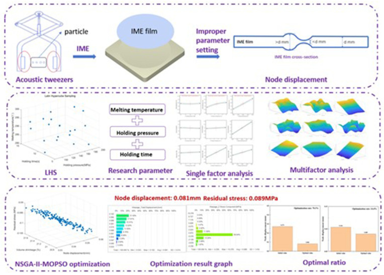
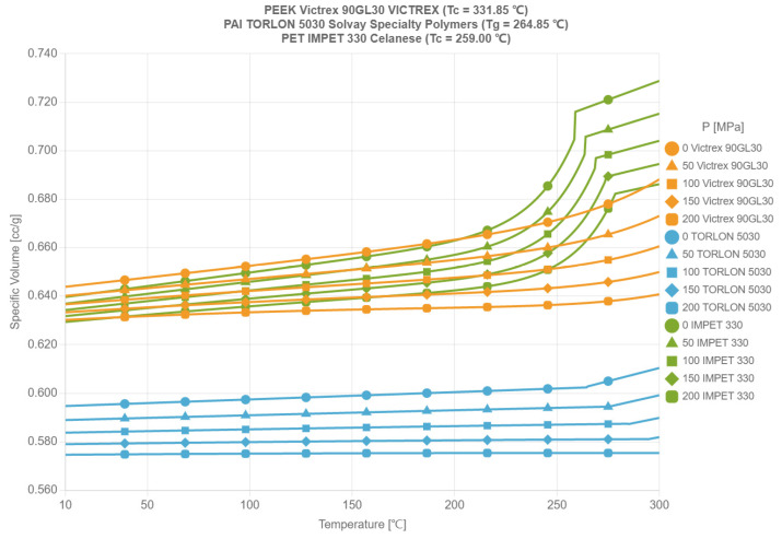
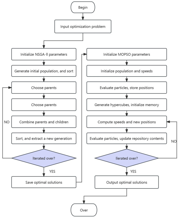
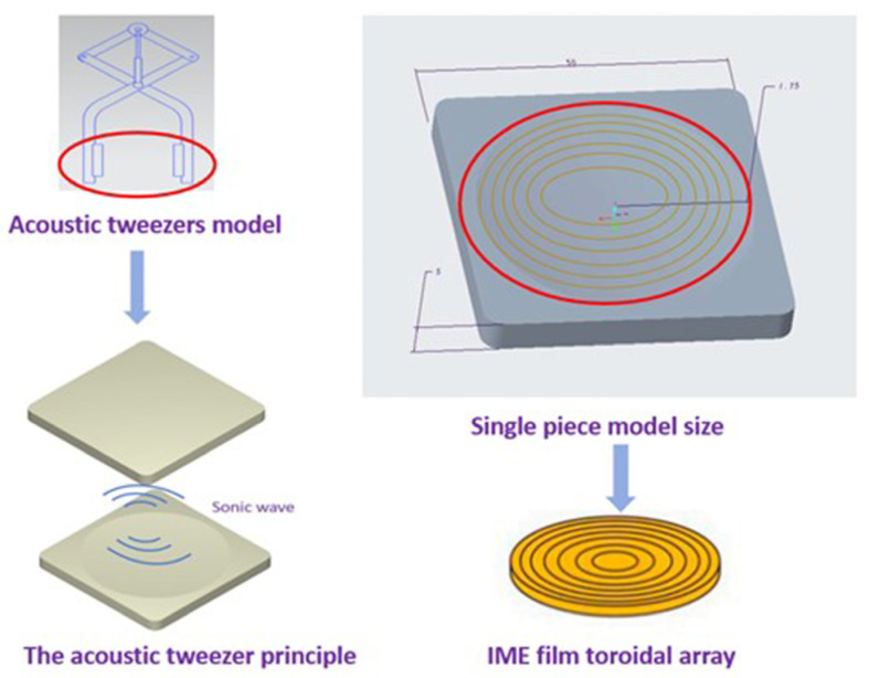
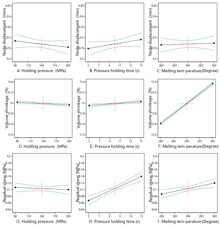
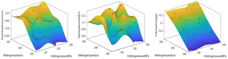
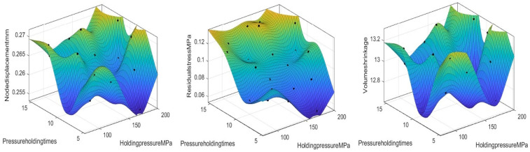
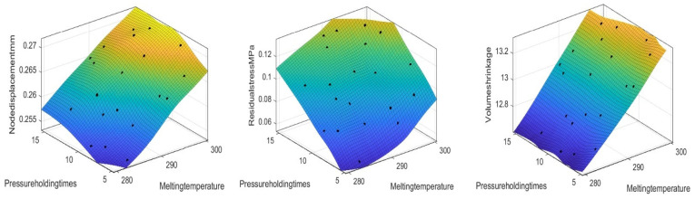
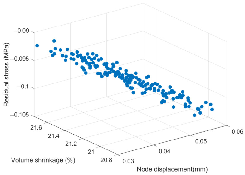
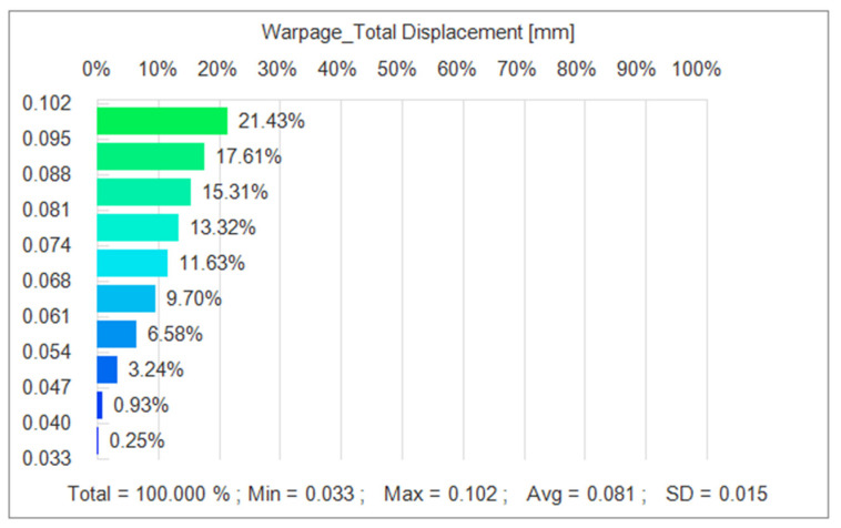
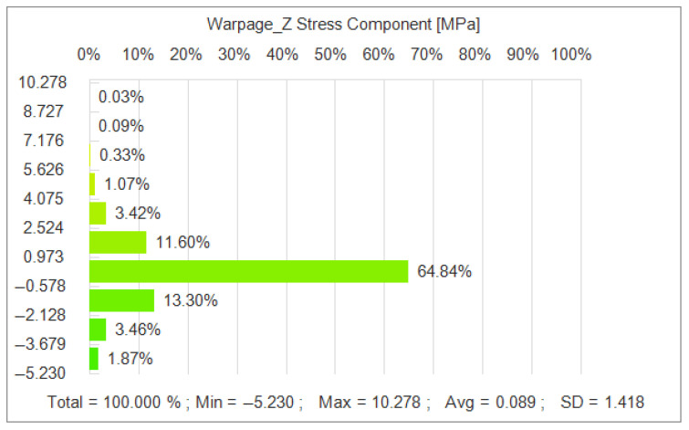
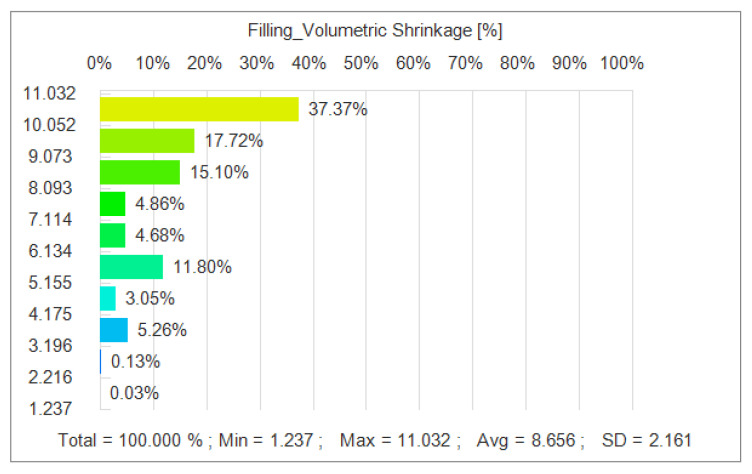
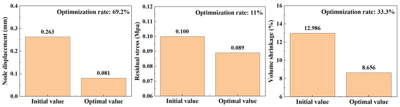
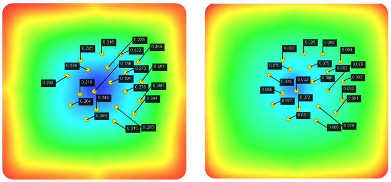
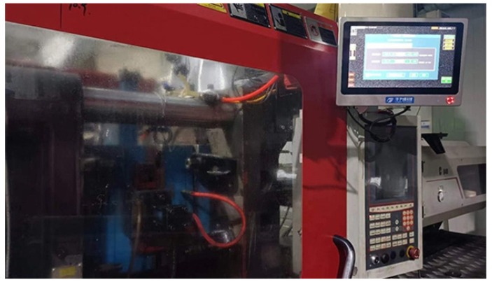
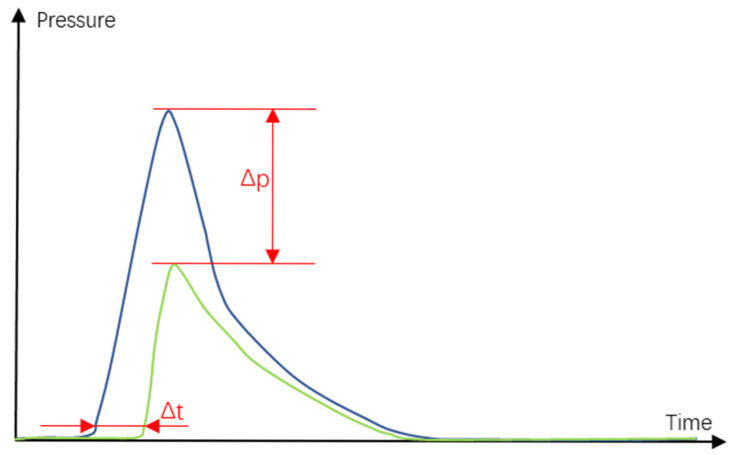
Acoustic tweezers, as advanced micro/nano manipulation tools, play a pivotal role in biomedical engineering, microfluidics, and precision manufacturing. However, piezoelectric-based acoustic tweezers face performance limitations due to multi-physical coupling effects during microfabrication. This study proposes a novel approach using injection molding with embedded electronics (IMEs) technology to fabricate piezoelectric micro-ultrasonic transducers with micron-scale precision, addressing the critical issue of acoustic node displacement caused by thermal-mechanical coupling in injection molding-a problem that impairs wave transmission efficiency and operational stability. To optimize the IME process parameters, a hybrid multi-objective optimization framework integrating NSGA-II and MOPSO is developed, aiming to simultaneously minimize acoustic node displacement, volumetric shrinkage, and residual stress distribution. Key process variables-packing pressure (80-120 MPa), melt temperature (230-280 °C), and packing time (15-30 s)-are analyzed via finite element modeling (FEM) and validated through in situ tie bar elongation measurements. The results show a 27.3% reduction in node displacement amplitude and a 19.6% improvement in wave transmission uniformity compared to conventional methods. This methodology enhances acoustic tweezers' operational stability and provides a generalizable framework for multi-physics optimization in MEMS manufacturing, laying a foundation for next-generation applications in single-cell manipulation, lab-on-a-chip systems, and nanomaterial assembly.
Keywords: IME technology; NSGA-II-MOPSO; acoustic tweezers; micro/nano manufacturing; multi-objective optimization; thermal–mechanical coupling; wave transmission efficiency.
Conflict of interest statement
The authors declare no conflicts of interest.
Figures

Similar articles
-
Short-Term Memory Impairment.2024 Jun 8. In: StatPearls [Internet]. Treasure Island (FL): StatPearls Publishing; 2025 Jan–. 2024 Jun 8. In: StatPearls [Internet]. Treasure Island (FL): StatPearls Publishing; 2025 Jan–. PMID: 31424720 Free Books & Documents.
-
Multiobjective optimization of CO2 injection under geomechanical risk in high water cut oil reservoirs using artificial intelligence approaches.Sci Rep. 2025 Jul 15;15(1):25643. doi: 10.1038/s41598-025-10111-0. Sci Rep. 2025. PMID: 40664954 Free PMC article.
-
Using Adaptive Surrogate Models to Accelerate Multi-Objective Design Optimization of MEMS.Micromachines (Basel). 2025 Jun 26;16(7):753. doi: 10.3390/mi16070753. Micromachines (Basel). 2025. PMID: 40731662 Free PMC article.
-
Management of urinary stones by experts in stone disease (ESD 2025).Arch Ital Urol Androl. 2025 Jun 30;97(2):14085. doi: 10.4081/aiua.2025.14085. Epub 2025 Jun 30. Arch Ital Urol Androl. 2025. PMID: 40583613 Review.
-
Coupling Agents in Acoustofluidics: Mechanisms, Materials, and Applications.Micromachines (Basel). 2025 Jul 19;16(7):823. doi: 10.3390/mi16070823. Micromachines (Basel). 2025. PMID: 40731732 Free PMC article. Review.
References
-
- Friend J., Yeo L.Y. Microscale acoustofluidics: Microfluidics driven via acoustics and ultrasonics. Rev. Mod. Phys. 2011;83:647–704. doi: 10.1103/RevModPhys.83.647. - DOI
Grants and funding
LinkOut - more resources
Full Text Sources
Miscellaneous
