

Semi-stationary Multi-source AI-powered Real-time Tomography
- PMID: 40808799
- PMCID: PMC12341843
- DOI: 10.1109/trpms.2024.3433575
Semi-stationary Multi-source AI-powered Real-time Tomography
Abstract
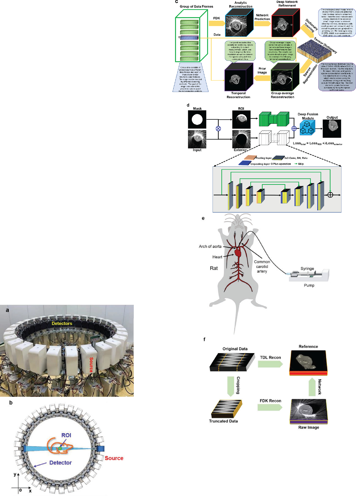
Over the past decades, the development of CT technologies has been largely driven by the need for cardiac imaging but the temporal resolution remains insufficient for clinical CT in difficult cases and rather challenging for preclinical CT since small animals have much higher heart rates than humans. To address this challenge, here we report a Semi-stationary Multi-source AI-based Real-time Tomography (SMART) CT system. This unique scanner is featured by 29 source-detector pairs fixed on a circular track to collect X-ray signals in parallel, enabling instantaneous tomography in principle. Given the multisource architecture, the field-of-view only covers a cardiac region. To solve the interior problem, an AI-empowered interior tomography approach is developed to synergize sparsity-based regularization and learning-based reconstruction. To demonstrate the performance and utilities of the SMART system, extensive results are obtained in physical phantom experiments and animal studies, including dead and live rats as well as live rabbits. The reconstructed volumetric images convincingly demonstrate the merits of the SMART system using the AI-empowered interior tomography approach, enabling cardiac CT with the unprecedented temporal resolution of 33ms, which enjoys the highest temporal resolution than the state of the art.
Keywords: Computed tomography (CT); cardiac imaging; deep learning; image reconstruction; multi-source; preclinical imaging; real-time.
Figures


Similar articles
-
Prescription of Controlled Substances: Benefits and Risks.2025 Jul 6. In: StatPearls [Internet]. Treasure Island (FL): StatPearls Publishing; 2025 Jan–. 2025 Jul 6. In: StatPearls [Internet]. Treasure Island (FL): StatPearls Publishing; 2025 Jan–. PMID: 30726003 Free Books & Documents.
-
Short-Term Memory Impairment.2024 Jun 8. In: StatPearls [Internet]. Treasure Island (FL): StatPearls Publishing; 2025 Jan–. 2024 Jun 8. In: StatPearls [Internet]. Treasure Island (FL): StatPearls Publishing; 2025 Jan–. PMID: 31424720 Free Books & Documents.
-
In silico modeling of a clinical photon-counting CT system: Verification and validation.Med Phys. 2025 Jun;52(6):3840-3853. doi: 10.1002/mp.17886. Epub 2025 May 13. Med Phys. 2025. PMID: 40491044
-
A rapid and systematic review of the clinical effectiveness and cost-effectiveness of paclitaxel, docetaxel, gemcitabine and vinorelbine in non-small-cell lung cancer.Health Technol Assess. 2001;5(32):1-195. doi: 10.3310/hta5320. Health Technol Assess. 2001. PMID: 12065068
-
The Black Book of Psychotropic Dosing and Monitoring.Psychopharmacol Bull. 2024 Jul 8;54(3):8-59. Psychopharmacol Bull. 2024. PMID: 38993656 Free PMC article. Review.
References
-
- Achenbach S, Moshage W, Ropers D, Nossen J, and Daniel WG, “Value of electron-beam computed tomography for the noninvasive detection of high-grade coronary-artery stenoses and occlusions,” New England Journal of Medicine, vol. 339, no. 27, pp. 1964–1971, 1998. - PubMed
-
- Kambadakone AR, and Sahani DV, “Body perfusion CT: technique, clinical applications, and advances,” Radiologic Clinics of North America, vol. 47, no. 1, pp. 161–178, 2009. - PubMed
-
- Buzug TM, “Computed tomography,” Springer handbook of medical technology, pp. 311–342: Springer, 2011.
-
- Primak AN, McCollough CH, Bruesewitz MR, Zhang J, and Fletcher JG, “Relationship between noise, dose, and pitch in cardiac multi–detector row CT,” Radiographics, vol. 26, no. 6, pp. 1785–1794, 2006. - PubMed
-
- Russo V, Garattoni M, Buia F, Attinà D, Lovato L, and Zompatori M, “128-slice CT angiography of the aorta without ECG-gating: efficacy of faster gantry rotation time and iterative reconstruction in terms of image quality and radiation dose,” European radiology, vol. 26, no. 2, pp. 359–369, 2016. - PubMed
Grants and funding
LinkOut - more resources
Full Text Sources
Miscellaneous