Review
. 2025 Aug 27;15(37):30490-30551.
doi: 10.1039/d5ra04623h. eCollection 2025 Aug 22.

Nanographene horizons: the emerging role of hexa- peri-hexabenzocoronene in functional material design

Affiliations
Review

Nanographene horizons: the emerging role of hexa- peri-hexabenzocoronene in functional material design

Ehsan Ullah Mughal et al. RSC Adv. .

Abstract

Hexa-peri-hexabenzocoronene (HBC) and its derivatives have emerged as prominent polycyclic aromatic hydrocarbons (PAHs) due to their unique structural, electronic, and photophysical properties. This review provides a comprehensive overview of the synthetic strategies employed for the construction of HBC frameworks, ranging from traditional methods to recent advances that offer improved efficiency, regioselectivity, and structural diversity. The molecular architecture of HBCs, characterized by extended π-conjugation and planarity, contributes significantly to their stability and distinctive physical properties, including high charge-carrier mobility and tunable optical absorption. We further highlight the multifaceted applications of HBC-based materials, particularly in the realm of organic and optoelectronic devices, where their excellent semiconducting behavior and strong π-π stacking facilitate their use in organic field-effect transistors (OFETs), organic photovoltaics (OPVs), and organic light-emitting diodes (OLEDs). Their roles in energy storage, especially in supercapacitors and battery systems, are also discussed, focusing on their ability to enhance charge storage and cycling stability. Moreover, HBCs have demonstrated potential as catalytic platforms and chemical sensors due to their electron-rich surfaces and functionalizable peripheries. Finally, the incorporation of HBC derivatives in biomedical fields such as bioimaging and drug delivery is reviewed, with emphasis on their biocompatibility, fluorescence properties, and structural adaptability. Overall, this article underscores the significant progress in HBC research and its expanding role in diverse scientific and technological domains.


Conflict of interest statement

The authors have no conflict of interest to declare.

Figures

Fig. 1
Fig. 1. Different regions of polycyclic hydrocarbons.
Fig. 2
Fig. 2. (a) Graphene sheet and (b) HBC (1).
Fig. 3
Fig. 3. Absorption (solid line) and fluorescence spectra (dashed line) of HBC. Reproduced from ref. with permission from Elsevier, Copyright © 2023.
Scheme 1
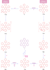
Scheme 1. Different routes for the synthesis of HBC core molecule.
Scheme 2
Scheme 2. Scholl reaction for the conversion of HBP to HBC, the proposed mechanism for arenium ion (A) and radical cation (B) respectively.
Fig. 4
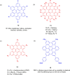
Fig. 4. Different structures of functionalized HBC molecules (a) symmetrical 6-, 12-, and 18-fold substituted HBCs (b) core–shell structure (c) (a and b) symmetrical 6-, 12-, and 18-fold substituted HBCs (d) Gemini-shaped amphiphilic HBCs.
Fig. 5
Fig. 5. HBC derivatives incorporating diverse functional groups for applications in optical absorption, cross-linking, hydrogen bonding, and related functionalities.
Fig. 6
Fig. 6. Core structure of FHBC derivatives incorporating pendant arylamines, thiophenes, porphyrins, and fullerenes.
Fig. 7
Fig. 7. Structure of HBCs-based triptycenes. Reproduced from ref. with permission from Elsevier, Copyright © 2014.
Scheme 3
Scheme 3. Synthesis of HBC porphyrin using (i) 0.5 equiv. tetracyclone (ii) 1 equiv. 3,5-di-tert-butylbenzaldehyde, 3 equiv. pyrrole, trifluoroacetic acid (TFA), CH2Cl2 and DDQ 19% yield (iii) 16 equiv. dry FeCl3/CH3NO2 (300 mg mL−1), CH2Cl2, 0 °C, 2.5 h, >90% yield.
Fig. 8
Fig. 8. Synthesis of c-HBC using CSA strategy.
Fig. 9
Fig. 9. Structural representation of phenylene-extended cyclic HBCs synthesized by using cyclodehydrogenation reaction. Reproduced from ref. with permission from John Wiley & Sons, Copyright © 2015, Wiley-VCH Verlag GmbH & Co. KGaA, Weinheim.
Fig. 10
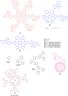
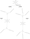
Fig. 10. Structures of HBC derivatives that were synthesized.
Fig. 11
Fig. 11. Molecular representation of HBC-AQ, -NMI, and -PMI.
Scheme 4
Scheme 4. Synthetic route for xylyl-substituted HBBNC 53; full-carbon congener.
Fig. 12
Fig. 12. Synthesis of dicyanomethyl HBC dimers. Reproduced from ref. with permission from the Royal Society of Chemistry.
Fig. 13
Fig. 13. Synthetic strategy for [4]CHBC. Reproduced from ref. with permission from John Wiley & Sons, Copyright © 2017, Wiley-VCH Verlag GmbH & Co. KGaA, Weinheim.
Fig. 14
Fig. 14. Structural representation of spiro-fused bis-HBC (SB-HBC).
Fig. 15
Fig. 15. Structural representation of four triads. Reproduced from ref. with permission from the Royal Society of Chemistry.
Fig. 16
Fig. 16. Structural representation of HBC tetrabenzoporphyrin architectures.
Scheme 5
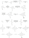
Scheme 5. Synthesis of HBC-based helicene. (a) Zn, TiCl4, THF, 70 °C, 22 h; (b) Br2, CHCl3, rt, 30 min; (c) KOtBu, THF, 0 °C, 20 min; (d) Ph2O, 260 °C in microwave reactor, 12 h; (e) FeCl3, CH3NO2, CH2Cl2, 0 °C, 100 min.
Scheme 6
Scheme 6. Synthetic approach for synthesis of 7-helical HBC. Reproduced from ref. with permission from John Wiley & Sons, Copyright © 2021, Wiley-VCH Verlag GmbH & Co. KGaA, Weinheim.
Fig. 17
Fig. 17. Azepine-embedded seco-HBC-based helix nanographenes.
Scheme 7
Scheme 7. Synthesis of aza-nanographenes 84a and 84b.
Scheme 8
Scheme 8. Sonogashira coupling reaction producing hexabenzocoronene derivatives 85–88.
Scheme 9
Scheme 9. Synthesis of HBC-6BTZA.
Scheme 10
Scheme 10. Synthesis of tetracyanoethylene-bridged HBC dimer and trimer.
Fig. 18
Fig. 18. Structure of the RuII sandwich complex with hexa-tert-butyl HBC.
Scheme 11
Scheme 11. Synthesis of mPHBC (A) and pPHBC.
Scheme 12
Scheme 12. Synthesis of p-HBC-4Si7116 and p-HBC-6Si7117.
Fig. 19
Fig. 19. Chemical structures of functional HBC–alkyne by Sonogashira coupling reaction.
Scheme 13
Scheme 13. Synthetic route towards HBC–AOM 135.
Scheme 14
Scheme 14. Synthesis of F3-HBC. (a) N2, AlCl3, CH2Cl2, 0 °C, r. t., 1 h; (b) N2, SiCl4, EtOH, 0 °C, r. t., 22 h; (c) Ar, Pd(PPh3)4, K2CO3, toluene, EtOH, H2O, 110 °C, 19 h; (d) N2, DDQ, TfOH, CH2Cl2, 0 °C, r. t., 2 h; (e) N2, Pd(dppf)Cl2, K3PO4, toluene, H2O, 100 °C, 23 h; (f) N2, Pd(dppf)Cl2, K3PO4, toluene, H2O, 100 °C, 17 h; (g) H5IO6, KI, H2SO4, 0 °C, r. t., 4 d.
Scheme 15
Scheme 15. Synthesis of the target ligand and complexes of HBC.
Scheme 16
Scheme 16. Synthesis of oxygen-doped NG, sulfur-doped NGs, and selenium-doped NGs.
Scheme 17
Scheme 17. Synthesis of fused porphyrin NiFP1.
Fig. 20
Fig. 20. Chemical representation of tris-iodinated HBC derivatives synthesized using Suzuki coupling reaction.
Fig. 21
Fig. 21. Crystal structure and packing of HBC 1.
Fig. 22
Fig. 22. Diagram representing the packing arrangements in nanotubes ((a)–(c)). Reproduced from ref. with permission from American Chemical Society, Copyright © 2008.
Fig. 23
Fig. 23. Diagrammatic illustration of the experimental assembly (left) and 2D WAXS pattern of HBC scaffold 28 represent intra- and intercolumnar organization (right). Reproduced from ref. with permission from American Chemical Society, Copyright © 2005.
Fig. 24
Fig. 24. Schematic representation of top (a), side view (b) and crystal packing of HBC-based triptycenes (c). Reproduced from ref. with permission from Elsevier, Copyright © 2014.
Fig. 25
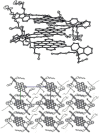
Fig. 25. The thermal ellipsoid representation of the FHBC structure (top) and the crystal packing arrangement (bottom) along the a-axis are depicted. Reproduced from ref. with permission from American Chemical Society, Copyright © 2014.
Fig. 26
Fig. 26. Supramolecular arrangements of mesogens in mesosphere. Reproduced from ref. with permission from John Wiley & Sons, Copyright © 2016, Wiley-VCH Verlag GmbH & Co. KGaA, Weinheim.
Fig. 27
Fig. 27. X-ray crystal representation of (a) 60a and (b) 60b along with top and side view of (c) 60a and (d) 60b. Reproduced from ref. with permission from the Royal Society of Chemistry.
Fig. 28
Fig. 28. Frontier MOs and optimized geometry of [4]CHBC: (a) molecular structure top view; (b) molecular structure side view; (c) [4]CHBC HOMO; (d) [4]CHBC LUMO. Reproduced from ref. with permission from John Wiley & Sons, Copyright © 2017, Wiley-VCH Verlag GmbH & Co. KGaA, Weinheim.
Fig. 29
Fig. 29. Crystal structure analysis of SB-HBC: (a) top-down perspective, (b) lateral perspective, and (c) molecular arrangement of SB-HBC within a single unit cell. Reproduced from ref. , https://doi.org/10.1039/C8CC07405D, under the terms of the CC BY-NC 3.0 license, https://creativecommons.org/licenses/by-nc/3.0/.
Fig. 30
Fig. 30. WAXS profile of four triads HBC-2POSS. Reproduced from ref. with permission from the Royal Society of Chemistry.
Fig. 31
Fig. 31. (a) HBC derivatives with C1- and D3h-symmetry (where n represents the alkyl chain length). (b) HBC-C12 with D6h-symmetry.
Fig. 32
Fig. 32. Top (a) and side (b) views X-ray crystallographic structures of NG 84a with 50% probability of thermal ellipsoids. Reproduced from ref. with permission from John Wiley & Sons, Copyright © 2024, Wiley-VCH Verlag GmbH & Co. KGaA, Weinheim.
Fig. 33
Fig. 33. Semi-empirical methods were used to calculate the top and side views of structure of 177 (for example C3 symmetry) along with the chemical structure. Reproduced from ref. with permission from John Wiley & Sons, Copyright © 2025, Wiley-VCH Verlag GmbH & Co. KGaA, Weinheim.
Fig. 34
Fig. 34. (a) 2D-WAXS image of HBC-6BTZA (b) Schematic representation of the columnar organization and STM pictures of the HBC-6BTZA-formed bilayer at the TCB/HOPG interface. (b) (a) Large-scale STM image of the bilayer (b) Small-scale STM image. Reproduced from ref. with permission from John Wiley & Sons, Copyright © 2025, Wiley-VCH Verlag GmbH & Co. KGaA, Weinheim.
Fig. 35
Fig. 35. Schematic packing model of p-HBC-6Si7 LamColr structure (a), LamColr structure HBC core arrangement (b), and p-HBC-6Si7 Colh structure schematic packing model (c). The ODMS chains and HBC cores are shown by the red lines and green discs, respectively.
Fig. 36
Fig. 36. HBC derivatives for photovoltaic applications.
Fig. 37
Fig. 37. Devices based on vacuum sublimated HBC and their photovoltaic performance. Reproduced from ref. with permission from John Wiley & Sons, Copyright © 2012, Wiley-VCH Verlag GmbH & Co. KGaA, Weinheim.
Fig. 38
Fig. 38. Schematic representation of the columnar stacks of star-shaped dyads (left) and interdigitating stacks of the linear dyad (right). Reproduced from ref. with permission from American Chemical Society, Copyright © 2012.
Fig. 39
Fig. 39. (Left) Current density–voltage characteristics of polymer/PC71BM-based PSCs with AM 1.5 G, 100 mW cm−2 illumination (right) features of the current density and voltage of PSC devices of PHBCDPPC8 and PHBCDPPDT following processing with DIO additive under 100 mW cm−2 of AM 1.5 G illumination. Reproduced from ref. with permission from Elsevier, Copyright © 2016.
Fig. 40
Fig. 40. Molecular structure of BHB.
Fig. 41
Fig. 41. Graphical representation of brush-coated molecularly aligned HBCs films and application in thin-film transistors. Reproduced from ref. with permission from American Chemical Society, Copyright © 2019.
Fig. 42
Fig. 42. Graphical representation of polysubstituted hexa-cata-HBC and its applications in transistors. Reproduced from ref. with permission from American Chemical Society, Copyright © 2019.
Fig. 43
Fig. 43. Diagrammatic representation of the layer-by-layer synthesis of SURMOFs based on HPB-1 and HBC-1 linkers. Reproduced from ref. with permission from John Wiley & Sons, Copyright © 2024, Wiley-VCH Verlag GmbH & Co. KGaA, Weinheim.
Fig. 44
Fig. 44. (a) Diagram showing the assembling of HBC on an electrode and it's in situ electrochemical production. (b) Representative cyclic voltammograms of the HBC assembly on ITO, obtained in a 6 M KOH solution at different scan speeds between 5 and 500 mV s−1. Reproduced from ref. with permission from John Wiley & Sons, Copyright © 2015, Wiley-VCH Verlag GmbH & Co. KGaA, Weinheim.
Fig. 45
Fig. 45. Diagrammatic representation of SG films for planar MSCs on a Si/SiO2 wafer produced from SHBC. Reproduced from ref. with permission from American Chemical Society, Copyright © 2017.
Fig. 46
Fig. 46. Dynamic hierarchical assembly of nano-graphene to reorganize and modify (above) and TEM picture of the multi-stage self-assembly structure of nanographene (below) Reproduced from ref. with permission from Springer, Copyright © 2019.
Fig. 47
Fig. 47. Li-ion battery cell voltage and the plot of eternal energy change for Li and Li+ adsorption on various HBC-based nanosheets. Reproduced from ref. with permission from Elsevier, Copyright © 2020.
Fig. 48
Fig. 48. The most stable N-HBC:Ca complex's (a) optimized framework, (b) MEP plot, (c) HOMO, and (d) LUMO profiles. Reproduced from ref. with permission from Elsevier, Copyright © 2024.
Fig. 49
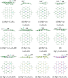
Fig. 49. Optimized structures of Mg adsorbed on (a) C42H18, (b) o-C40H18N2, (c) m-C40H18N2 (d) p-C40H18N2, (e) o-C40H18BN, (f) m-C40H18BN, (g) p-C40H18BN, (h) C38H18B2N2, (i) C36H18B3N3, (j) C28H18Si14, (k) C21H18Si21, and (l) B21H18N21. Reproduced from ref. with permission from the Royal Society of Chemistry.
Fig. 50
Fig. 50. AlN-HBC:GBL complex's (a) optimized structure, (b) MEP, (c) HOMO, and (d) LUMO profiles. Distances are measured in Å. Reproduced from ref. with permission from Elsevier, Copyright © 2021.
Fig. 51
Fig. 51. AlN-HBC:FRU complex's (a) optimized structure and (b) MEP profile. Distances are measured in Å. Reproduced from ref. with permission from Elsevier, Copyright © 2022.
Fig. 52
Fig. 52. (a) Hydrogenation of HBC nanographene in the direction of an archetype ((b) and (c)) Au(111) sample at the EI-TOF-MS measurement location within the chamber. Reproduced from ref. with permission from American Chemical Society, Copyright © 2023.
Fig. 53
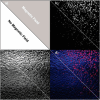
Fig. 53. Images of cells labeled with PEG-PE micelles that coentrap H2 and magnetic nanoparticles using magnetically guided two-photon stimulated fluorescence microscopy. The sample's upper right triangle was subjected to a magnet. (a) A schematic representation of the region where a magnetic field is applied; (b) fluorescence from micelles tagged with H2; (c) transmission; and (d) merged images for transmission and fluorescence. Reproduced from ref. with permission from American Chemical Society, Copyright © 2007.
Fig. 54
Fig. 54. Diagrammatic illustration of the two-step template approach. Reproduced from ref. with permission from American Chemical Society, Copyright © 2009.
Fig. 55
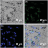
Fig. 55. HepG2 cells treated to 10 μg per mL Fe3O4/HBC@F127 nanocomposites for 24 hours were shown in CLSM pictures. Bright-field (A), Fe3O4/HBC@F127 nanocomposites (B), DAPI (C), and the combined image of (A)–(C) are shown in (D). Reproduced from ref. with permission from the Royal Society of Chemistry.
Fig. 56
Fig. 56. (a) Optimized structure and (b) computed MEP plot of the NHBC (c) optimized structure (d) PDOS plot of the NHBC–BCNU complex. Reproduced from ref. with permission from Elsevier, Copyright © 2024.
Fig. 57
Fig. 57. Molecular structures of both series TPSi and HBCSi respectively.
Fig. 58
Fig. 58. The chemical structure of FHBC(TDPP)2 (185) is characterized by an acceptor–π–donor–π–acceptor (A–π–D–π–A) configuration, where the central HBC moiety functions as the electron-donating core (D). Reproduced from ref. with permission from John Wiley & Sons, Copyright © 2019, Wiley-VCH Verlag GmbH & Co. KGaA, Weinheim.
Fig. 59
Fig. 59. Molecular structure of HBC derivatives with three diacetylene-containing and three alkyl side chains in alternating positions (HBC-1,3,5-Cm,n-DA R).
Fig. 60
Fig. 60. Structural representation of HBC-1,3,5-Cm,n-DA-C6,8.
Fig. 61
Fig. 61. Molecular structure of HBC-1,3,5-Ph-C12.
Fig. 62
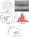
Fig. 62. (a) The molecular representation of TSHBC. (b) SEM image of the device of FTO/TiO2/perovskite/TSHBC film. The best IV characteristics (c) comparison of the performance distributions of 30 individual devices (d) of the cells. (e) The efficiency variation of the devices stored under illumination at AM 1.5 G with the humidity of 45%. Reproduced from ref. with permission from American Chemical Society, Copyright © 2015.
Fig. 63
Fig. 63. DFT structure of TM-02 efficient for perovskite solar cells along with its inverted planar configuration. Reproduced from ref. with permission from John Wiley & Sons, Copyright © 2023, Wiley-VCH Verlag GmbH & Co. KGaA, Weinheim.
Fig. 64
Fig. 64. (a) The FTO/m-TiO2/perovskite/HTM/Au device structure is shown schematically, with PyMAI acting as an interface modifier between the perovskite and HBC-DPA(Me)OMe (b) PCE using the ISOS-D-2I protocol as a function of aging time at 85 °C. Reproduced from ref. with permission from American Chemical Society, Copyright © 2023.
Fig. 65
Fig. 65. Polyarene-based HBC perovskite solar cells. Reproduced from ref. with permission from John Wiley & Sons, Copyright © 2025, Wiley-VCH Verlag GmbH & Co. KGaA, Weinheim.

Similar articles

  • Prescription of Controlled Substances: Benefits and Risks.
    Preuss CV, Kalava A, King KC. Preuss CV, et al. 2025 Jul 6. In: StatPearls [Internet]. Treasure Island (FL): StatPearls Publishing; 2025 Jan–. 2025 Jul 6. In: StatPearls [Internet]. Treasure Island (FL): StatPearls Publishing; 2025 Jan–. PMID: 30726003 Free Books & Documents.
  • Molecular Gridization of Organic Semiconducting π Backbones.
    Yang T, Tang Y, Wei Y, Xie L, Huang W. Yang T, et al. Acc Chem Res. 2025 Jul 1;58(13):1982-1996. doi: 10.1021/acs.accounts.5c00180. Epub 2025 Jun 13. Acc Chem Res. 2025. PMID: 40512962
  • Management of urinary stones by experts in stone disease (ESD 2025).
    Papatsoris A, Geavlete B, Radavoi GD, Alameedee M, Almusafer M, Ather MH, Budia A, Cumpanas AA, Kiremi MC, Dellis A, Elhowairis M, Galán-Llopis JA, Geavlete P, Guimerà Garcia J, Isern B, Jinga V, Lopez JM, Mainez JA, Mitsogiannis I, Mora Christian J, Moussa M, Multescu R, Oguz Acar Y, Petkova K, Piñero A, Popov E, Ramos Cebrian M, Rascu S, Siener R, Sountoulides P, Stamatelou K, Syed J, Trinchieri A. Papatsoris A, et al. Arch Ital Urol Androl. 2025 Jun 30;97(2):14085. doi: 10.4081/aiua.2025.14085. Epub 2025 Jun 30. Arch Ital Urol Androl. 2025. PMID: 40583613 Review.
  • Electrophoresis.
    Sonagra AD, Zubair M, Dholariya SJ. Sonagra AD, et al. 2025 Jul 14. In: StatPearls [Internet]. Treasure Island (FL): StatPearls Publishing; 2025 Jan–. 2025 Jul 14. In: StatPearls [Internet]. Treasure Island (FL): StatPearls Publishing; 2025 Jan–. PMID: 36251838 Free Books & Documents.
  • Interventions to improve safe and effective medicines use by consumers: an overview of systematic reviews.
    Ryan R, Santesso N, Lowe D, Hill S, Grimshaw J, Prictor M, Kaufman C, Cowie G, Taylor M. Ryan R, et al. Cochrane Database Syst Rev. 2014 Apr 29;2014(4):CD007768. doi: 10.1002/14651858.CD007768.pub3. Cochrane Database Syst Rev. 2014. PMID: 24777444 Free PMC article.

References

    1. Novoselov K. S. Geim A. K. Morozov S. V. Jiang D. Zhang Y. Dubonos S. V. Grigorieva I. V. Firsov A. A. Science. 2004;306:666–669. - PubMed
    1. Novoselov K. S. Jiang D. Schedin F. Booth T. J. Khotkevich V. V. Morozov S. V. Geim A. K. Proc. Natl. Acad. Sci. U. S. A. 2005;102:10451–10453. - PMC - PubMed
    1. Geim A. K. Novoselov K. S. Nat. Mater. 2007;6:183–191. - PubMed
    1. Novoselov K. S. Fal′ko V. I. Colombo L. Gellert P. R. Schwab M. G. Kim K. Nature. 2012;490:192–200. - PubMed
    1. Chen W. Xiao P. Chen H. Zhang H. Zhang Q. Chen Y. Adv. Mater. 2019;31:1802403. - PubMed