. 2025 Sep 5;11(36):eady2069.
doi: 10.1126/sciadv.ady2069. Epub 2025 Sep 5.

Adaptive superposition compound eyes for perceptions under distinct light levels

Affiliations

Adaptive superposition compound eyes for perceptions under distinct light levels

Heng Jiang et al. Sci Adv. .

Abstract

Optical superposition natural compound eyes (OSNCEs) allow circadian insects to thrive in varying light conditions thanks to their unique anatomical structures. This provides a blueprint for optical superposition artificial compound eyes (OSACEs) that can adapt to different illumination intensities. However, OSACEs have received limited research attention until recently, with most studies focusing on apposition compound eyes that operate only in bright light. In this work, we accurately replicate the anatomical features and the ganglia adjustments of OSNCEs using lensed plastic optical fibers as artificial ommatidia. As the core part of this work, we implement a spatial approach alongside a temporal approach derived from both hardware and algorithms to accommodate lighting variations of up to 1000 times while still maintaining high image quality such as 180° field of view, minimal distortion, nearly infinite depth of field, and ultrafast motion detection. These adaptive biomimetic features make the OSACE very promising for surveillance, virtual reality, and unmanned aerial vehicles.


Figures

Fig. 1.
Fig. 1.. Concept and principle of the OSACE that uses lensed optical fibers to mimic natural counterparts.
(A) Moth has NCEs that can work during both day and night. (B) During the day, each facet lens with a half aperture angle μ, an aperture diameter A, and a focal length f focuses light on the corresponding rhabdoms through a long crystalline tract. Each rhabdom then transmits the signal to the medulla and lobula through synaptic connections within lamina cartridges. (C) At night, the pigment migration allows light from neighboring ommatidia to focus on one rhabdom with an effective half aperture angle μ¯ , an effective aperture diameter A¯ , and an effective focal length f¯ . Lateral neural connections between rhabdoms facilitate the Gaussian spatial summation of signal outputs. (D and E) Schematic diagram of a moth’s NCE imaging results during the day (D) and night (E). (F) OSACE effectively replicates natural structures during day time by using microlenses to emulate facet lenses and crystalline cones, optical fiber cores to simulate the rhabdom, optical fiber claddings to mimic pigment cells, an imaging lens to replicate the synaptic units to facilitate the signal transmission to deeper neural centers, photodetectors to mimic photoreceptor cells, and a flat imaging sensor chip to emulate deeper neural centres (medulla and lobula), where initial signal processing occurs. Subsequently, the signals are conveyed to the central processing unit (CPU) of a computer for advanced analysis. (G) OSACE effectively emulates its natural counterparts at night by transitioning from the scatter mode to the focus mode and the binning mode, mirroring the phenomenon of pigment migration, facilitating lateral interactions among captured spots on the planar imaging sensor chip to replicate the lateral neural connections.
Fig. 2.
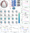
Fig. 2.. Operating principles of the OSACE.
(A) Scanning electron microscopy (SEM) image of the conical microlensed plastic optical fiber. (B) Top view of the OSACE light receiving head with a 3D printed dome to host 271 fiber-lensed ends. (C) 3D view of an assembled OSACE. (D) Concept of image formation. Under a varying intensity of illumination, a + line-art object pattern is projected to the camera head. Then, certain fibers receive light and subsequently transmit this pattern from the lensed end to the opposite end of the fiber. In conditions of sufficient illumination, an imaging lens is operated in the scatter mode to project the overlapping spots onto a flat imaging sensor chip. Conversely, under weak light conditions, the imaging lens is switched to the focus mode, resulting in discrete spots on the chip, which subsequently undergo lateral interactions. As a result, a final digital image can be generated across varying light intensities.
Fig. 3.
Fig. 3.. Static imaging and depth estimation of the OSACE.
(A) Combined image of a laser spot captured from nine angles (−90° to 90° in both x and y directions, 22.5° increment). The center of each recorded laser spot image is overexposed, appearing as a white spot. (B) Depth estimation based on the linear correlation between the point spread parameter σ and the reciprocal of object distance (u−1). Sample images at u1 = 3 mm, u2 = 5 mm, u3 = 7 mm, and u4 = 9 mm are delineated within the dotted box. For each image obtained at these distances, gray values along five vertical edge lines (two shown in pink) in the x direction are analyzed to calculate the mean and error, as shown in (H) and (J). DL denotes the distance from a point on the pink line to the image’s upper boundary. (C to F) Images of the letter F under different conditions. (D) Real-time images without grayscale mapping, Gaussian, or temporal enhancement. (G) Information entropy of images under different light intensities; SD < 0.01; mean and error from five repeated tests. (H) Information entropy using spatial or temporal processing at 0.1 lux, with results averaged over five tests. (I) Structural similarity index measure (SSIM) of images at various light intensities, SD < 0.03; based on three repeated experiments. (J) Relationship between σ and u−1 under different light intensities. (K) Ratio of edge pixels to total nonzero pixels versus u−1 at 0.1 lux. (L) Relationship between σ and u−1 under different exposure times at 0.1 lux. a.u., arbitrary unit.
Fig. 4.
Fig. 4.. Panoramic imaging and nearly infinite depth of field of the OSACE.
(A to C) Images of the letters “HK” acquired at three distinct polar angles relative to the center of the OSACE: −50° (left), 0° (center), and +50° (right), under varying light intensities. (D) Diagram of an experimental configuration designed to validate the near-infinite depth of field capability of OSACE under hierarchical light intensities. Objects A (circle) and B (triangle) are positioned at angular orientations of −40° and 40°, respectively. (E to G) Images of the circle and triangle patterns captured with the circle image fixed at a distance of DA = 1 mm, while the distance of the triangle image shifts from DB = 1, 5, to 10 mm under various illumination intensities.
Fig. 5.
Fig. 5.. Dynamic motion detection of the OSACE.
(A) Diagram illustrating the positioning of the OSACE 10 mm in front of a checkerboard pattern, followed by its translation at different velocities under varying illumination intensities. (B) Optical flow when the OSACE is translated referring to a checkerboard pattern at a distance of 10 mm. Here, the white area is illuminated by bright squares of the checkerboard, while the black area corresponds to the dark squares of the checkerboard. The direction and length of the vectors indicate the motion direction and velocity of a bright square. (C to E) Relationships between measured velocities and true velocities under 100 lux (C), 50 lux (D), and 10 lux (E), respectively. Optical flow is used to compute velocities, which subsequently undergo a correction process before curve fitting for each light intensity condition.

References

    1. R. Hooke, Micrographia, or Some Physiological Descriptions of Minute Bodies, made by Magnifying Glasses, with Observations and Inquiries Thereupon (Council of the Royal Society of London, 1664).
    1. S. Exner, Die Physiologie der facettirten Augen von Krebsen und Insecten: Eine Studie (Franz Deuticke, 1891).
    1. M. F. Land, Variations in the Structure and Design of Compound Eyes (Springer, 1989).
    1. Jiang H., Tsoi C. C., Yu W. X., Ma M. C., Li M. J., Wang Z. K., Zhang X. M., Optical fibre based artificial compound eyes for direct static imaging and ultrafast motion detection. Light Sci Appl 13, 256 (2024). - PMC - PubMed
    1. Warrant E. J., Seeing better at night: Life style, eye design and the optimum strategy of spatial and temporal summation. Vision Res. 39, 1611–1630 (1999). - PubMed