. 2025 Sep 8;14(1):311.
doi: 10.1038/s41377-025-02024-4.

Position-correlated biphoton wavefront sensing for quantum adaptive imaging

Affiliations

Position-correlated biphoton wavefront sensing for quantum adaptive imaging

Yi Zheng et al. Light Sci Appl. .

Abstract

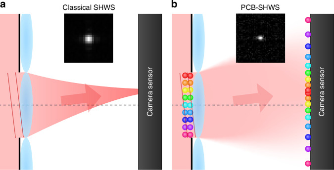
Quantum imaging with spatially entangled photons offers advantages such as enhanced spatial resolution, robustness against noise, and counterintuitive phenomena, while a biphoton spatial aberration generally degrades its performance. Biphoton aberration correction has been achieved by using classical beams to detect the aberration source or scanning the correction phase on biphotons if the source is unreachable. Here, a new method named position-correlated biphoton Shack-Hartmann wavefront sensing is introduced, where the phase pattern added on photon pairs with a strong position correlation is reconstructed from their position centroid distribution at the back focal plane of a microlens array. Experimentally, biphoton phase measurement and adaptive imaging against the disturbance of a plastic film are demonstrated. This single-shot method is a more direct and efficient approach toward quantum adaptive optics, suitable for integration into quantum microscopy, remote imaging, and communication.


Conflict of interest statement

Conflict of interest: The authors declare no competing interests.

Figures

Fig. 1
Fig. 1
Principle of classical SHWS and PCB-SHWS. For simplicity, we show the light fields from a single aperture. a Classical SHWS. The inset shows a focused spot inside a microlens aperture with a width 300 μm using an 808-nm laser as the light source, taken by the EMCCD with the EM gain set to 0. b PCB-SHWS. At the microlens and its back focal plane, respectively, two balls with the same color represent an entangled photon pair. A tilt phase leads to the centroid displacement. The inset is the biphoton centroid marginal distribution inside an aperture from our phase measurement experiment
Fig. 2
Fig. 2
Experimental setup of PCB-SHWS. The laser passes through a beam shaping system (not shown) and pumps the BBO crystal. Degenerate collinear type-I down-converted photons from the BBO pass through the first Fourier lens L1, the half-wave plate (HWP), the object, and the second Fourier lens L2, and are reflected by the SLM. A plastic film may be pasted in front of the SLM. Then, they pass through a 4f system L3,L4 and is incident on the microlens array. An imaging lens L5 images the optical field at the microlens back focal plane to the EMCCD sensor. IF1: long-pass interference filter; IF2: bandpass filter. In the imaging experiment, the EMCCD sensor is moved to the image plane together with IF2 (see Supplementary Information 3 for the setup)
Fig. 3
Fig. 3. Biphoton phase measurement result.
The calculated Legendre coefficients (excluding L0,0, on the left of each panel) and phase distributions (on the right of each panel) are shown for the five cases: a no phase, b a saddle phase, c Legendre modes, d a plastic film, and e the film with correction. The gradient distribution of the no-phase case is the reference of the other cases
Fig. 4
Fig. 4
Adaptive imaging result. The direct images (without pixel binning, normalized according to the maximum and minimum value), CPDs with the other photon postselected to a certain pixel (the red cross), centroid marginal distributions without background removal (the horizontal and vertical bright lines are noises from the summation which are present in all three cases, but in the no-film and film with correction case, they are less significant because the peaks are much brighter), and joint probabilities of anti-correlated pixel pairs are shown for the a no-film, b film, and c film with correction case. The image sizes are 2.678 × 1.794 mm

References

    1. Zhang, Z. S. et al. Entanglement-based quantum information technology: a tutorial. Adv. Opt. Photonics16, 60–162 (2024).
    1. Moreau, P. A. et al. Imaging with quantum states of light. Nat. Rev. Phys.1, 367–380 (2019).
    1. Defienne, H. et al. Advances in quantum imaging. Nat. Photonics18, 1024–1036 (2024).
    1. Pittman, T. B. et al. Optical imaging by means of two-photon quantum entanglement. Phys. Rev. A52, R3429–R3432 (1995). - PubMed
    1. Lemos, G. B. et al. Quantum imaging with undetected photons. Nature512, 409–412 (2014). - PubMed

LinkOut - more resources