Review
. 2025;221(6):81.
doi: 10.1007/s11214-025-01210-5. Epub 2025 Sep 9.

Simulation Models for Exploring Magnetic Reconnection

Affiliations
Review

Simulation Models for Exploring Magnetic Reconnection

Michael Shay et al. Space Sci Rev. 2025.

Abstract

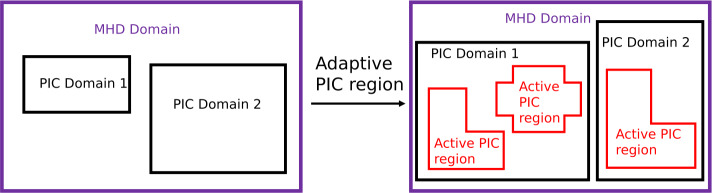
Simulations have played a critical role in the advancement of our knowledge of magnetic reconnection. However, due to the inherently multiscale nature of reconnection, it is impossible to simulate all physics at all scales. For this reason, a wide range of simulation methods have been crafted to study particular aspects and consequences of magnetic reconnection. This article reviews many of these methods, laying out critical assumptions, numerical techniques, and giving examples of scientific results. Plasma models described include magnetohydrodynamics (MHD), Hall MHD, Hybrid, kinetic particle-in-cell (PIC), kinetic Vlasov, Fluid models with embedded PIC, Fluid models with direct feedback from energetic populations, and the Rice Convection Model (RCM).

Keywords: Magnetic reconnection; Magnetosphere; Numerical methods; Plasma physics; Plasma simulation; Solar corona; Turbulence.


Conflict of interest statement

Competing InterestsThe authors have no competing interests to declare that are relevant to the content of this article.

Figures

Fig. 1
Fig. 1
Physics of the Hall effect in reversing magnetic fields. A reversing anti-parallel magnetic field in the ±xˆ direction is drawn using black arrows, with the neutral line as the dashed line. A uniform electric field in the zˆ direction is drawn in green. The smaller blue trajectory is that of an electron E×B drifting towards the neutral line with bulk velocity ue. An ion E×B drifting far from the neutral line has bulk ion velocity ui identical to ue, so the electric field in this region is given by E=u×B/c, where u is the single fluid (MHD) bulk flow velocity. Within an ion gyroradius rLi of the neutral line, the electron continues with bulk flow ue, while the ion demagnetizes (in the red trajectory) and ui becomes small. In this region, there is a non-zero current density J (orange), and the electric field in this region is predominantly given by the Hall electric field E=J×B/neec
Fig. 2
Fig. 2
Sketch of how the Hall effect impacts linear waves in MHD. The wave structure for (a) shear Alfvén waves, (b) parallel propagating whistler waves, and (c) kinetic Alfvén waves. The equilibrium magnetic field By0 is the dashed black arrow. The perturbed magnetic field B1 are the black arrows. The perturbed ion bulk flow ui are the red arrows, which occur in (a) because the wavelength is much larger than the ion gyroradius. In (b) and (c), the wavelength is at or below ion gyroscales, so the bulk flow is due to electron motion in the blue arrows. In (c), there is a large out-of-plane equilibrium magnetic field Bz0, so the magnetic perturbation Bz1 changes the magnetic pressure which to first order and requires a change to the gas pressure p
Fig. 3
Fig. 3
“GEM Challenge” result showing Hall-MHD simulations faithfully obtain the rate of change of reconnected flux obtained in kinetic models. The legend describes the simulation approach for each curve; resistive-MHD is far slower than the other models. Adapted from Birn et al. (2001)
Fig. 4
Fig. 4
Pressure and out-of-plane magnetic field in Hall MHD reconnection simulations. The legend describes the simulation approach for each curve; resistive-MHD is far slower than the other models. Adapted from Rogers et al. (2003)
Fig. 5
Fig. 5
Evolution of (a) out-of-plane electric field Ey at the X-point (x=0, z=0) and (b) root-mean-square value of the normal component of magnetic field Bz evaluated over the length of the reconnecting current sheet (between two outflow regions) Vertical dashed lines mark the times at which Ey attains its peak value Eypeak for different values of the current sheet half-thickness ϵ. (c) Scaling of Eypeak with ϵ (in log -scale) from simulations (blue circles) and a fit Eypeak=0.05/ϵ1.15 (red line). Adapted from Jain and Sharma (2015b)
Fig. 6
Fig. 6
Yee lattice and electric and magnetic fields in a cell in a 3D case, where the length of each side is Δx. Electric fields E are defined at the midpoint of each side of the cube, while magnetic fields B are defined at the center of each face of the cube. In a 2D case, all the quantities are defined in the x-y plane, projecting each position onto the cell in the x-y plane
Fig. 7
Fig. 7
2D PIC simulation result for magnetotail reconnection. (a) Electron fluid velocity Vex, (b) electron temperature Te, (c) zoom-in view of Te, and (d) the heating term in Eq. (65). Adapted from Hesse et al. (2018a, 2019)
Fig. 8
Fig. 8
Simulation results overplotted with magnetic field lines. (a) The JE term from Poynting’s theorem; (b) In-plane electron flow field; (c) EN, the normal component of the electric field; (d) E, the component of the electric field parallel to the magnetic field; (e) BMBM,0, the change in the out-of-plane component of the magnetic field from its (spatially constant) initial value; (f) SL, the horizontal component of the Poynting flux. Adapted from Swisdak et al. (2018)
Fig. 9
Fig. 9
3D PIC simulation results. (a) 3D view of reconnection with a limited X-line extent, where the thin current sheet region extends 30di in y (Huang et al. 2020). The mass ratio in the simulation is 25. (b) The current density on the x=0 plane (left) and magnetic field Bz on the z=0 plane (middle and right) (Liu et al. 2019). The mass ratio is 75. The gray shaded area represents the “suppressed reconnecting region”. Adapted from Huang et al. (2020) and Liu et al. (2019)
Fig. 10
Fig. 10
An example of particle trajectory analysis. Adapted from Oka et al. (2010)
Fig. 11
Fig. 11
(a) An example of guiding-center drift analysis. Particle energization due to different drift currents for electrons (top) and ions (bottom). jc is due to particle curvature drift. jg is due to particle grad-B drift. jm is due to magnetization. j=jc+jg+jm. Ke˙ and Ki˙ are the energy change rates for electrons and ions, respectively. They are all normalized by mec2ωpe. (b) Similar to (a) but shows energy dependent values (Li et al. 2019b) at a given time. Adapted from Li et al. (2017)
Fig. 12
Fig. 12
PIC simulations of reconnection in shocks. (a) 2D simulation domain and the current density Jz. (b) Electron fluid velocity Vex. (c) Ion fluid velocity Vix. (d) 3D simulation domain and the current density Jz. Adapted from Bessho et al. (2019) and Ng et al. (2022)
Fig. 13
Fig. 13
A schematic shows the improvement of the MHD-AEPIC (right) model from the MHD-EPIC (left) model. Adapted from Chen et al. (2023)
Fig. 14
Fig. 14
Evolution of FTEs. Viewed from the Sun, a series of snapshots are shown with magnetic field lines colored by ion velocity uiz[km/s]. Adapted from Chen et al. (2017)
Fig. 15
Fig. 15
Energetic electron spectra from kglobal. A log-log plot of the electron differential density F(W) versus energy (W) at multiple times from a reconnection simulation with a guide field Bg/B0=0.25. A power-law develops after t/τA35. Inset: The late-time F(W) for several guide fields, illustrating the dependence on the ratio of the guide-to-ambient magnetic field. Adapted from Arnold et al. (2021)
Fig. 16
Fig. 16
Sketch of the typical sampling of the plasma distribution function f(x,v) adopted in PIC (left) and Eulerian (methods). Adapted from Finelli (2022)
Fig. 17
Fig. 17
Magnetic reconnection modeled using three different codes (HVM, HVLF and PIC). Left: normalized reconnection rate R/B0vA. The inset shows the time interval corresponding to the ticker curves in the main plot. To ease the comparison, the curves in the inset are shifted in time. Right: (first row) out-of-reconnection-plane magnetic field ΔBz/B0=(BzBz(t=0))/B0 showing the expected Hall quadrupolar pattern; (second row) electric field parallel to the ambient magnetic field E/E, where E is the root mean square of E in the shown region; (third row) current density in the out-of-plane direction Jz; (fourth row) electron current density in the plane Je(inplane). The superposed black or white curves are the magnetic field lines. The three columns show results from the three different models. The left column show results from HVM at the simulation time t=237.5Ωcp1; the center column show results from the HVLF code at the simulation time t=232.5Ωcp1; the right column show results from the PIC code at the simulation time t=235.0Ωcp1. Ωcp is the proton cyclotron frequency. Adapted from Finelli et al. (2021)
Fig. 18
Fig. 18
(a) Plasma β; (b) proton Vz. The black lines show the magnetic field lines. (c) Magnetic field strength (black solid) and plasma density (red dashed) fluctuations from the virtual spacecraft location indicated with the black dot in panel (a). The anticorrelation between magnetic field and density fluctuations is compatible with mirror mode waves. Adapted from Hoilijoki et al. (2017)
Fig. 19
Fig. 19
Evolution of the magnetotail current sheet in a 3D-3V Vlasiator simulation. The panels show the current sheet surface (defined as Br=0) at different times, t=1300s (a), t=1400s (c), t=1470s (g). The color of the surface corresponds to the current density J. The yellow line indicates the flow reversal between the Earthward and tailward reconnection outflow. The magenta and green lines are locations where Br=0 and Bz=0 and correspond to X-lines and O-lines (differentiated using the sign of Bz/r, which is positive at the X-lines and negative at the O-lines). The primary reconnection line is where the X-line (magenta) and flow reversal (yellow) contours are approximately co-located. The background grid shows the coordinates but also the magnetic-field topology: the black grid shows areas where the magnetic field is directed northward, and the white grid shows the areas where it is southward-directed. Adapted from Palmroth et al. (2023)

References

    1. Adhikari S, Parashar TN, Shay MA, Matthaeus WH, Pyakurel PS, Fordin S, Stawarz JE, Eastwood JP (2021) Energy transfer in reconnection and turbulence. Phys Rev E 104:065206 - PubMed
    1. Adhikari S, Yang Y, Matthaeus WH, Cassak PA, Parashar TN, Shay MA (2024) Scale filtering analysis of kinetic reconnection and its associated turbulence. Phys Plasmas 31(2):020701
    1. Akhavan-Tafti M, Palmroth M, Slavin JA, Battarbee M, Ganse U, Grandin M, Le G, Gershman D, Eastwood JP, Stawarz J (2020) Comparative analysis of the Vlasiator simulations and MMS observations of multiple X-line reconnection and flux transfer events. J Geophys Res Space Phys 125(7):e2019JA027410. 10.1029/2019JA027410
    1. Alho M, Wedlund CS, Nilsson H, Kallio E, Jarvinen R, Pulkkinen T (2019) Hybrid modeling of cometary plasma environments. Astron Astrophys 630:A45. 10.1051/0004-6361/201834863
    1. Alho M, Battarbee M, Pfau-Kempf Y, Khotyaintsev YV, Nakamura R, Cozzani G, Ganse U, Turc L, Johlander A, Horaites K, Tarvus V, Zhou H, Grandin M, Dubart M, Papadakis K, Suni J, George H, Bussov M, Palmroth M (2022) Electron signatures of reconnection in a global evlasiator simulation. Geophys Res Lett 49(14):e2022GL098329. 10.1029/2022GL098329