. 2025 Aug 29;25(17):5360.
doi: 10.3390/s25175360.

MINISTAR to STARLITE: Evolution of a Miniaturized Prototype for Testing Attitude Sensors

Affiliations

MINISTAR to STARLITE: Evolution of a Miniaturized Prototype for Testing Attitude Sensors

Vanni Nardino et al. Sensors (Basel). .

Abstract

Star trackers are critical electro-optical devices used for satellite attitude determination, typically tested using Optical Ground Support Equipment (OGSE). Within the POR FESR 2014-2020 program (funded by Regione Toscana), we developed MINISTAR, a compact electro-optical prototype designed to generate synthetic star fields in apparent motion for realistic ground-based testing of star trackers. MINISTAR supports simultaneous testing of up to three units, assessing optical, electronic, and on-board software performance. Its reduced size and weight allow for direct integration on the satellite platform, enabling testing in assembled configurations. The system can simulate bright celestial bodies (Sun, Earth, Moon), user-defined objects, and disturbances such as cosmic rays and stray light. Radiometric and geometric calibrations were successfully validated in laboratory conditions. Under the PR FESR TOSCANA 2021-2027 initiative (also funded by Regione Toscana), the concept was further developed into STARLITE (STAR tracker LIght Test Equipment), a next-generation OGSE with a higher Technology Readiness Level (TRL). Based largely on commercial off-the-shelf (COTS) components, STARLITE targets commercial maturity and enhanced functionality, meeting the increasing demand for compact, high-fidelity OGSE systems for pre-launch verification of attitude sensors. This paper describes the working principles of a generic system, as well as its main characteristics and the early advancements enabling the transition from the initial MINISTAR prototype to the next-generation STARLITE system.

Keywords: Optical Ground Support Equipment (OGSE); optical stimulator; star field simulation; star tracker.


Conflict of interest statement

Authors Cristian Baccani, Vasco Milli and Jacopo Pini were employed by the company GESTIONE SILO S.R.L. Authors Massimo Ceccherini, Massimo Cecchi and Fabrizio Manna were employed by the company PROMEL COSTRUZIONI S.R.L. Authors Francesco Focardi, Enrico Franci and Lorenzo Salvadori were employed by the company SAITEC S.R.L. The remaining authors declare that the research was conducted in the absence of any commercial or financial relationships that could be construed as a potential conflict of interest.

Figures

Figure 1
Figure 1
(a) Celestial coordinate system and declination and right ascension angles DEC and RA. RA angle is measured along the celestial parallel starting at the Vernal Equinox (one of the intersection points between the ecliptic and the celestial equator circles) and ranging from 0 to 360°. The DEC angle measures the angular distance from the celestial equator, ranging from −90° to +90°. (b) Tait–Bryan angles describing the roll, pitch, and yaw angles around, respectively, the x, y, and z axes. (c) The roll, pitch, and yaw angles and the x, y, and z axes in the Celestial Sphere reference frame.
Figure 2
Figure 2
The star catalog is divided into multiple spatially overlapping sub-catalogs. The angular width of each region is large enough to contain the FOV of the simulated scene. The direction of view is used to select the sub-catalog of interest, so only stars entering the FOV of the simulated scene are selected for applying the inverse rotation matrix, bringing them into the star tracker’s optical head reference frame.
Figure 3
Figure 3
The 2 × 2 pixel matrices used for representing the position of a star with sub-pixel precision. The gray level of each pixel represents its luminance value 0 (black) to 255 (white). The star position lies in the barycenter of the 2 × 2 pixel distribution, and the sum of the pixel values over the matrix gives the luminance value associated with the star. The use of a 2 × 2 pixel matrix allows for varying the barycenter position both in the horizontal (matrices left to right) and I vertical directions (matrices top to bottom) in the range of ±1/2 pixel (segmented square) around the 2 × 2 matrix center. Note that only variations in the upper rightmost quadrant are shown due to the symmetry of the problem.
Figure 4
Figure 4
Logic flux of the mathematical model providing the representation of the observed scene by the generic star tracker’s optical head. Pre-allocation represents the “slow” computation phase. Such architecture allows fast (real-time) computation on a limited set of celestial bodies (both stars and non-stellar objects) at the simulation phase. Disturbance effects are input into the simulation before the rendering of the simulated scene. Model-related blocks are highlighted in grey, and general system software execution is in white.
Figure 5
Figure 5
MINISTAR and STARLITE star tracker validation system architecture. Input data (outlined in gray) are processed by a workstation, providing the dynamic, real-time rendering of the scene on the instrument’s display and projected after collimation into the star tracker optical head under test. Star tracker output data (outlined in black) can be analyzed, allowing checks in both open and closed-loop configurations.
Figure 6
Figure 6
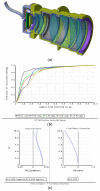
(a) MINISTAR optics and mechanical mounting. (b) Encircled energy for the MINISTAR optical system (generated by Zemax OpticStudio). (c) Optical system field curvature and distortion (generated by Zemax OpticStudio).
Figure 7
Figure 7
Edmund lenses RMS spot radius (in mrad, afocal mode) for different angles for the case of (a) an RGB source; and (b) for the red channel only. The resulting angular resolution is inferior to the theoretical limit imposed by the display pixel size, primarily due to lens-induced aberrations.
Figure 8
Figure 8
One of the STARLITE current shelves realized with 3D printing, mounting the Kowa 35 mm objective LM35XC by Kowa Optimed, Deutschland GmbH (Duesseldorf, Germany). STARLITE supports standard C-mount optics, enabling flexible FOV adjustment via interchangeable objectives.
Figure 9
Figure 9
(a) The diagram shows the MINISTAR optics-distorted pixels (crosses) versus the ideal (regularly spaced) coordinates (black grid). By knowing the regularly spaced coordinates in the input, the optics-induced distortion can be mapped and corrected. (b) Distortion mapping experimental setup. The MINISTAR prototype (on the left) projects the point grid on the camera (right).
Figure 10
Figure 10
Spectral radiance of the red MINISTAR display channel R rMSΔλ (dotted), the spectrum of the calibrated source HL-3P-INT-CAL with Lambertian diffuser (continuous), and the normalized spectral response of the DALSA 1M60 detector (dashed line).
Figure 11
Figure 11
Visual magnitude comparison for a set of selected stars: the magnitude values simulated by the MINISTAR (after calibration) are shown in grey, and the corresponding values of apparent magnitude from the HIPPARCOS star catalog are shown in black.
Figure 12
Figure 12
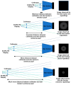
Vignetting problem: As the separation between the STARLITE exit pupil and the entrance pupil of the star tracker under test increases, a growing portion of the emitted rays falls outside the acceptance aperture of the star tracker, leading to increased vignetting.
Figure 13
Figure 13
STARLITE flange for mounting on baffle.
Figure 14
Figure 14
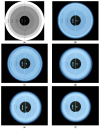
Vignetting with increasing distance between camera (simulating a star tracker) and STARLITE collimator. (a) Test image. (b) Minimal vignetting. (cf) Increasing vignetting with distance between STARLITE and the camera.

References

    1. Liebe C.C. Star Trackers for Attitude Determination. IEEE Aerosp. Electron. Syst. Mag. 1995;10:10–16. doi: 10.1109/62.387971. - DOI
    1. Bar-Itzhack I.Y. New Method for Extracting the Quaternion from a Rotation Matrix. J. Guid. Control Dyn. 2000;23:1085–1087. doi: 10.2514/2.4654. - DOI
    1. Park J.-O., Choi J.-Y., Lim S.-B., Kwon J.-W., Youn Y.-S., Chun Y.-S., Lee S.-S. Electrical Ground Support Equipment (EGSE) Design for Small Satellite. J. Astron. Space Sci. 2002;19:215–224. doi: 10.5140/JASS.2002.19.3.215. - DOI
    1. Dynamic Optical Ground Support Equipment. [(accessed on 26 June 2025)]. Available online: https://www.terma.com/media/gzrbpee2/terma_dogse_data_sheet.pdf.
    1. Samaan M., Steffes S., Theil S. Star Tracker Real-Time Hardware in the Loop Testing Using Optical Star Simulator; Proceedings of the Space Flight Meeting; New Orleans, LA, USA. 13–17 February 2011.

LinkOut - more resources