Review
. 2025 Oct;12(40):e11478.
doi: 10.1002/advs.202511478. Epub 2025 Sep 14.

Artificial Nervous Systems

Affiliations
Review

Artificial Nervous Systems

Lu Yang et al. Adv Sci (Weinh). 2025 Oct.

Abstract

Electronic devices and systems that can emulate the complex cognitive abilities of nervous systems have been an important research topic in recent years. Artificial nervous systems with multimodal perception, neural signal processing, and reflex-driven functionalities have been established by integrating multimodal sensors, neuromorphic synaptic devices, and effector units. The important value of artificial nervous systems is mainly embodied in bioinspired information processing, transmission, and environmental adaptation aspects. However, since this field is still in its early stages, more exploration is needed to realize artificial nervous systems with autonomous adaptability, intelligent feedback, and bio-interfacing applications. This review provides a comprehensive overview of recent advancements, spanning from the fundamental device structure and mechanism of synaptic devices to bio-inspired artificial nervous systems. Finally, a brief perspective of this research field is provided.

Keywords: artificial nervous system; multimodal perception; neural signal processing; neuromorphic device; synaptic device.


Conflict of interest statement

The authors declare no conflict of interest.

Figures

Figure 1
Figure 1
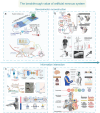
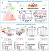
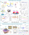
The biological nervous system and the artificial nervous system.
Figure 2
Figure 2
The breakthrough value of an artificial nervous system. a,b) The level of sensorimotor function reconstruction. Sensorimotor function simulation and substitution.[ 14 , 15 ] Copyright 2018, The American Association for the Advancement of Science. Sensorimotor function reconstruction.[ 14 , 15 ] Copyright 2023, The American Association for the Advancement of Science. Copyright 2024, The Author(s). c,d) The level of information interaction. Neurotransmitter detection.[ 18 , 19 ] Copyright 2022, The Author(s), under exclusive licence to Springer Nature Limited. Human–machine interaction.[ 20 , 21 ] Copyright 2019, American Chemical Society. Copyright 2019 WILEY‐VCH Verlag GmbH & Co. KGaA, Weinheim.
Figure 3
Figure 3
Biological nervous system. a) The central and peripheral nervous systems.[ 26 ] Copyright 2025, American Chemical Society. b) Structure of biological neurons and synapses. c) The transformation process from STP to LTP.[ 29 ] Copyright 2017, American Chemical Society.
Figure 4
Figure 4
Structure diagrams of different types of two‐ and three‐terminal artificial synaptic devices, based on the operation principles. a–d) Diagrams of two‐terminal synaptic devices: ECM (rely on the migration and redox reactions of metal ions under voltage conditions), VCM (rely on valence changes of cations and the migration of oxygen anions), PCM (rely on a reversible phase transition from the amorphous to the crystalline state through a joule heating process), FEM (rely on the spontaneous polarization reversal of ferroelectric materials under an applied electric field), respectively. e–h) FGT (rely on the electronic charge can migrate to the floating gate and be captured under the effect of gate voltage regulation), EDLT (rely on the ion migration in the gate dielectric layer and channel layer under gate voltage), ECT (rely on the ion migration in the gate dielectric and the channel with redox properties), FeFET (rely on changing the ferroelectric material's polarization state), respectively.[ 35 ] Copyright 2021, American Chemical Society.
Figure 5
Figure 5
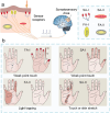
The mechanism of human tactile sensory transmission and distribution of different receptors in the palm. a) Schematic diagram of different parts of the skin's structure and four types of mechanoreceptors, and the process of sensory signal transduction in biological skin. b) Functions and receptive field sizes (left), and density distributions (right) of four types of mechanoreceptors.[ 111 ] Copyright 2016, Springer Nature Limited.
Figure 6
Figure 6
Four types of pressure sensors.[ 117 ] a) Resistive. b) Capacitive. c) Piezoelectric. d) Triboelectric. Used with permission of [S. Jena, A. Gupta.], from [Review on pressure sensors: A perspective from mechanical to micro–electro–mechanical systems. Sensor Review. 41(3), 320. and 2021 of copyright]; permission conveyed through Copyright Clearance Center, Inc.
Figure 7
Figure 7
The artificial afferent nerve system comprises pressure sensors and synaptic devices. Pressure sensors convert external pressures of different sizes into voltages of different amplitudes based on the negative piezoresistive effect, which will be coded and processed by a ring oscillator and the artificial synaptic device integrates the spatiotemporal information based on spike‐frequency‐dependent plasticity, and drives the effector by amplifying the postsynaptic current. a) Human afferent nerve that can sense pressure stimuli. b) Artificial afferent nerve's components. c) Image of the artificial tactile nerves. d) Postsynaptic current output under three different pressures (duration: 4 s). e) Postsynaptic current output at three different pressure intensities (pressure: 80 kPa). f) Maximum force of the biological muscle under varying pressures (duration: 0.5 s).[ 14 ] Copyright 2018, The American Association for the Advancement of Science. Schematic design of an artificial tactile neural system based on piezoresistive sensors, ionic cables, and synaptic devices. g) Illustration of the integration of different spatiotemporal information by tactile sensory neurons in the human tactile sensorimotor circuit. h) Comparison of sensory neurons (top) and the artificial tactile system (bottom). i) Schematic of the unit module of the artificial tactile system. j) Changes of sensor resistance and sensitivity at varying pressures. k) Paired‐pulse facilitation (PPF) response of synaptic devices.[ 143 ] Copyright 2018 WILEY‐VCH Verlag GmbH & Co. KGaA, Weinheim.
Figure 8
Figure 8
Schematic of an artificial tactile nervous system based on textured piezoresistive sensors and chitosan synaptic devices.a) Tactile afferent nerves. b) Artificial tactile sensory neurons. c) Simulated nociceptive perception function. (d) CAS and NBU Morse code. e) SOS Morse code signals at 7.84 kPa pressure with varying durations (short: 0.1 s, long: 0.5 s).[ 144 ] Copyright 2020, American Chemical Society. Functional validation diagrams of artificial tactile nervous systems. f) Transduction process of tactile signal. g) Working mechanism of the artificial perception and transmission nerve (APT).[ 145 ] Copyright 2020, The Author(s).
Figure 9
Figure 9
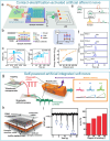
Self‐powered artificial tactile system based on nanogenerators and MoS2 artificial synapses. Self‐powered artificial tactile system based on TENG and MoS2 artificial synapses. TENG can convert external contact/friction stimuli, such as displacement, pressure, and other tactile stimulation modes, into electrical signals to stimulate synaptic devices. a) Schematic of artificial afferent nerves: including TENG, synaptic transistor, and functional circuit. b) Equivalent modeling diagram of components of the artificial afferent nerve. c) Excitatory postsynaptic currents (EPSC) responses at different distances. d) Ultralow energy consumption at single pulse (11.9 fJ/pulse). e) System equivalent schematic under dual‐TENG modulation. f) EPSC responses at different spatiotemporal stimulations.[ 146 ] Copyright 2021, The Author(s). g) Signal memory decoding process of soft neuro‐robots. h) Detailed structure of the system. i) EPSC and Bending angle of soft robot after different numbers of taps.[ 147 ] Copyright 2019, The American Association for the Advancement of Science.
Figure 10
Figure 10
Conceptual illustration of an artificial reflex arc system based on piezoresistive sensors, synaptic devices, and actuators. a) Comparison of the human (left) and artificial somatic reflex arc (right). b) Mimics the knee‐jerk reflex in biological systems, where the reflex is completed when the stimulus exceeds the activation threshold. c) Current response of the system at different pressures. d) Variation of TCU resistance with applied pressure. e) Response currents of the control circuit (Ictrl) and drive circuit (IAct) at above threshold pressure.[ 148 ] Copyright 2019 WILEY‐VCH Verlag GmbH & Co. KGaA, Weinheim.
Figure 11
Figure 11
Schematic of human visual pathways.[ 152 ]
Figure 12
Figure 12
Bio‐inspired visual memory systems comprise UV optical sensors and memristor devices. a) Visual information perception process in the human eyes. b) Equivalent schematic of the bio‐inspired visual memory system. c) I–V curves of the sensor under 350 nm illumination and dark conditions. d) I–V characteristics of the memristor device. e) I–V behavior of the system with/without UV illumination. f) Correlation mechanism between the sensor and memory device. g) Performance evaluation of the system's image‐pattern memorization capability.[ 196 ] Copyright 2018 WILEY‐VCH Verlag GmbH & Co. KGaA, Weinheim.
Figure 13
Figure 13
Architecture and performance of the artificial visual perception‐motor neural system.a) Photograph of the optoelectronic synapse. b) Artificial visual system comprising a photodetector, stretchable artificial synaptic device, circuit network, and artificial muscle. c) EPSC and PPF responses of the system under visible light. d, e) SDDP and SNDP responses under 0–100% mechanical strain. f) IPMC actuator's maximum displacement and front‐end device output voltage under 0–60 optical stimulation pulses. g) Deflections of the IPMC under 0–100 pulses.[ 197 ] Copyright 2018, The American Association for the Advancement of Science.
Figure 14
Figure 14
Artificial visual stimulus‐response system based on photodiodes and synaptic devices. a) Schematic of the human visual stimulus‐response pathway. b) Structural schematic of the photodiode. c) Architecture of the artificial synaptic device. d) Operational mechanism of the synaptic device. e) Synaptic response characteristics under varying stimuli. f) Trained learning process in a human subject (ball‐catching task) and corresponding neural signals. g) VNI and peak amplitude plots during different learning phases.[ 198 ] Copyright 2021, The American Association for the Advancement of Science.
Figure 15
Figure 15
Artificial visual nervous system based on perovskite photoelectric synapses. a) Light‐dependent sensory‐motor processes in the human visual system. b) Artificial visual neural system integrating perovskite synaptic devices, amplification circuits, and artificial muscle actuators. c–e) Relationships between EPSC and pulse duration, paired‐pulse facilitation (PPF) index versus inter‐pulse interval, and EPSC gain versus stimulus frequency under three distinct wavelengths (435, 545, and 700 nm). f) Dynamic variations in EPSC magnitude and corresponding artificial muscle tension under increase and decrease. g) Light intensities demonstrate adaptive bio‐inspired reflex modulation.[ 199 ] Copyright 2022 Elsevier Inc.
Figure 16
Figure 16
Artificial visual system based on helical‐structured synaptic devices. a) Schematic of biological and artificial visual neural system architectures. b,c) EPSC responses under DUV light with varying pulse widths and intensities. d) Ultralow energy consumption of the device.[ 200 ] Copyright 2023, American Chemical Society.
Figure 17
Figure 17
Artificial TENG‐synaptic auditory system and functional validation. a) Schematic of human auditory neural pathways. b) Architecture of the biomimetic auditory system. c) Voltage output spectrum of TENG across 50–5000 Hz frequency range. d) Acoustic intensity‐voltage correlation of TENG. e) Transfer characteristics of the synaptic device under TENG‐driven operation. f) EPSC amplitude modulation with frequency stimulation. g) Experimental setup for binaural sound source localization. h) Synaptic current amplitude ratio versus sound source azimuth (0°–180°).[ 206 ] Copyright 2020 Elsevier Ltd. All rights reserved.
Figure 18
Figure 18
Artificial synaptic device‐based auditory systems. a) Schematic illustrating action potential generation in the human auditory pathway under acoustic stimulation. b) Biomimetic neuromorphic auditory system integrating an energy conversion module (triboelectric/piezoelectric transducer) and synaptic plasticity emulation unit.[ 207 ] Copyright 2020, The Author(s). c) Circuit architecture of the artificial auditory neural network. d) Synaptically evoked postsynaptic currents under 5 Hz square‐wave acoustic stimulation.[ 208 ] Copyright 2019 Elsevier Ltd. All rights reserved. e) Biological integration mechanism of auditory‐spatial perception in human neurophysiology. f) Engineered bionic device replicating cochlear–vestibular multimodal integration. g) TENG output voltage versus sound pressure level at 180 Hz excitation. h) Frequency‐dependent TENG response under 110 dB acoustic input. i) Angular sensitivity characterization of TENG‐based acoustic localization. j) EPSC modulation correlated with sound source azimuth.[ 209 ] Copyright 2025 Elsevier B.V. All rights are reserved.
Figure 19
Figure 19
Biological taste signal transduction process.[ 221 ] Copyright 2023, American Chemical Society.
Figure 20
Figure 20
Artificial synapse‐based gustatory system and functional investigations. a) Schematic of signal transduction pathways in the human gustatory system. b) Biohybrid taste system. c) Hydrogen ion‐responsive mechanism in the acid‐sensing unit. d,e) pH‐dependent threshold voltage modulation characteristics. f) Spike frequency modulation under varying pH conditions. g) Sodium concentration‐dependent spiking patterns in the artificial taste‐sensing neuron.[ 227 ] Copyright 2022, American Chemical Society. h) Intelligent gustatory system with perceptual reflex capabilities for health monitoring and excess intake alert. i) Ion transport‐mediated entrapment mechanism in the artificial taste transduction pathway. j) Electrochemical impedance spectroscopy (EIS) spectra under different saline concentrations. k) Minimum activation voltage and corresponding EPSC across salt concentration gradients.[ 221 ] Copyright 2023, American Chemical Society.
Figure 21
Figure 21
Schematic of the human olfactory system.[ 228 ] Copyright 2023, The Author(s).
Figure 22
Figure 22
Artificial synaptic device‐based olfactory systems. a) Schematic of harmful gas effects on human olfactory receptors and organ systems. b) Operational model of the neuromorphic synaptic device. c) Response characteristics of the synaptic device under 20 ppm NO2 exposure. d) Real‐time current modulation under dual 20 ppm NO2 pulses with varying inter‐pulse intervals. e) PPF index at different pulse interval times.[ 237 ] Copyright 2019, Royal Society of Chemistry. f) Comparative schematics of biological and artificial olfactory pathways. g) Dynamic responses of SnO2/WO3 sensors to varying NH3/NO2 concentrations. h) NH3/NO2 concentration‐dependent response profiles of SnO2‐based artificial olfactory neurons. i) Gas discrimination characteristics of WO3‐based artificial olfactory neurons across concentration gradients.[ 238 ] 2022 The Authors. Advanced Science published by Wiley‐VCH GmbH.
Figure 23
Figure 23
a) Flexible olfactory neuromorphic device and corresponding mechanism diagram. b) excitatory inhibition function graph.[ 228 ] Copyright 2023, The Author(s). c) Schematic diagram of olfactory neuromorphic devices. d) Response characteristics under different concentrations of NO2 and NH3. e) Deflection angles of artificial muscles under different gas concentrations.[ 239 ] Copyright 2024 Wiley‐VCH GmbH.
Figure 24
Figure 24
Artificial Olfactory System Based on Sr‐ZnO Gas Sensor and Memristor.a) Schematic of the human olfactory system, comprising three key components: olfactory receptors, central processing centers, and effector muscles. b) Gas sensor responding to stimuli through voltage division modulation. c) Current–voltage (I–V) characteristics of the gas sensor under varying NH3 concentrations. d) Memristor current response modulation across NH3 concentration gradients. e) Transient current dynamics under low NH3 exposure (200 ppm). f) High‐concentration NH3 response (500 ppm) with saturation behavior.[ 240 ] Copyright 2021 Elsevier Ltd. All rights reserved.
Figure 25
Figure 25
Bimodal mechano–optical artificial neural systems. a) Schematic of visuotactile integration pathways in human sensory processing. b) Architecture of the artificial visuotactile neural system. c) Synaptic device response under varying light intensities. d) Pressure‐dependent synaptic modulation characteristics. e) Fusion output from equidistant multimodal inputs. f) Distance‐dependent response attenuation; g) Recognition accuracy comparison: unimodal versus bimodal fusion.[ 241 ] Copyright 2020, The Author(s). h) Mechanophotonic artificial synapse integrating TENG and graphene/MoS2 heterostructure. i) Synergistic modulation mechanism of mechanical displacement and optical signals. j) Synergistic current response under illumination and variable TENG gaps (0.75–1.5 mm) at VD = 1 V.[ 242 ] Copyright 2021, The American Association for the Advancement of Science.
Figure 26
Figure 26
Bimodal artificial nervous systems. a) Auditory‐tactile bimodal artificial nerve.[ 243 ] Copyright 2023 Wiley‐VCH GmbH. b) Multimodal sensory fusion system and corresponding signal conversion process.[ 244 ] Copyright 2021, The Author(s). c) Pressure–temperature bimodal perception system.[ 15 ] Copyright 2023, The American Association for the Advancement of Science.
Figure 27
Figure 27
a) Schematic architecture of the Braille‐reading neuromorphic module. b) Presynaptic spike frequency modulation characteristics under mechanical stimulation of the pressure sensor array (left), with corresponding postsynaptic current in a single‐pixel synaptic transistor (right). c) Minimum Victor‐Purpura distance between EPSC of different letters.[ 14 ] Copyright 2018, The American Association for the Advancement of Science. d) Time‐dependent current responses of the phalange‐mounted flexible sensor during 1–6.5 s flexion cycles. e) Operational schematic of the intelligent character‐writing interface. f) Distinctive current signatures corresponding to alphabetical character inputs.[ 245 ] Copyright 2019 WILEY‐VCH Verlag GmbH & Co. KGaA, Weinheim. g) ANN implementation framework for optical pattern recognition. h) Training image set containing characters “A” and “B” with progressive distortion levels. i) Performance metrics demonstrating 86.82% MNIST recognition accuracy across 20 training epochs.[ 246 ] Copyright 2021 Wiley‐VCH GmbH.
Figure 28
Figure 28
a) Dynamic correlation between pulse width modulation and joint flexion angles (left), with sequential snapshots demonstrating repetitive grasping motions of the neuro‐inspired robotic end‐effector (right).[ 16 ] Copyright 2023, The American Association for the Advancement of Science. b) System architecture of the BASE integrated on robotic manipulator surfaces (left), accompanied by its epidermal implementation schematic (right). c) Quantified ΔEPSC (excitatory postsynaptic current) variations reflecting spatial resolution of spherical object localization through BASE sensors.[ 241 ] Copyright 2020, The Author(s). d) Real‐time robotic hand manipulation sequences (upper panel) synchronized with ANN‐triggered voltage signals post‐learning optimization (lower panel), highlighting the system's reliability in conscious‐level motor emulation.[ 198 ] Copyright 2021, The American Association for the Advancement of Science.
Figure 29
Figure 29
a) Spatiotemporal mapping of EPSC across dorsal, lateral, and ventral epidermal regions during 50‐s locomotion cycles (left), with corresponding temporal profiles of soft neuromorphic robot kinematics (right).[ 147 ] Copyright 2019, The American Association for the Advancement of Science. b) Robotic hand reflex dynamics under finger percussion stimuli. c) Transient current modulations in electrochemical actuators correlating with applied pressure intensity.[ 144 ] Copyright 2019 WILEY‐VCH Verlag GmbH & Co. KGaA, Weinheim. d) Structural evolution of artificial muscle bundles: schematic illustrations (top) and photographic documentation (bottom) of knotting configurations with increasing filament multiplicity. e) Comparison of actuation strain versus input current density across multifilament assemblies. f) Correlation between strain rate enhancement and heating wire population in optimized muscle architectures.[ 247 ] Copyright 2024 Wiley‐VCH GmbH.
Figure 30
Figure 30
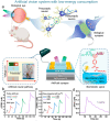
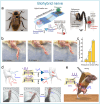
a) Hybrid system architecture: macroscopic view (left) and circuit schematic (right) of the artificial afferent‐biological efferent neural loop integrated with specimens.[ 14 ] Copyright 2018, The American Association for the Advancement of Science. b) Electrophysiological validation of the neuroprosthetic interface‐ photographic documentation of hindlimb withdrawal reflex in murine models with corresponding angular displacement measurements. c) The correlation between leg twitch angle and applied pressure.[ 15 ] Copyright 2023, The American Association for the Advancement of Science. d) Bipedal locomotion rehabilitation framework: implantable device schematic and sequential motion capture of knee flexion‐extension cycles. e) Diagram of a mouse using SNEN to restore autonomic motor function.[ 23 ] Copyright 2022, The Author(s).
Figure 31
Figure 31
Future roadmap and key challenges of the artificial nervous system.

References

    1. Attwell D., Laughlin S. B., J. Cerebr. Blood Flow Metab. 2001, 21, 1133. - PubMed
    1. Choi S., Yang J., Wang G., Adv. Mater. 2020, 32, 2004659. - PubMed
    1. Zheng Y., Xu H., Li Z., Li L., Yu Y., Jiang P., Shi Y., Zhang J., Huang Y., Luo Q., Adv. Mater. 2025, 37, 2504378. - PubMed
    1. Yuan Y., Zhong B., Qin X., Xu H., Li Z., Li L., Wang X., Zhang W., Lou Z., Fan Y., Nat. Commun. 2025, 16, 2681. - PMC - PubMed
    1. Li L., Xu H., Li Z., Zhong B., Lou Z., Wang L., Adv. Mater. 2025, 37, 2414054. - PubMed

LinkOut - more resources