. 2025 Sep 25;20(9):e0332263.
doi: 10.1371/journal.pone.0332263. eCollection 2025.

Measurement accuracy of CT systems: The importance of calibration phantoms

Affiliations

Measurement accuracy of CT systems: The importance of calibration phantoms

Jan Scherberich et al. PLoS One. .

Abstract

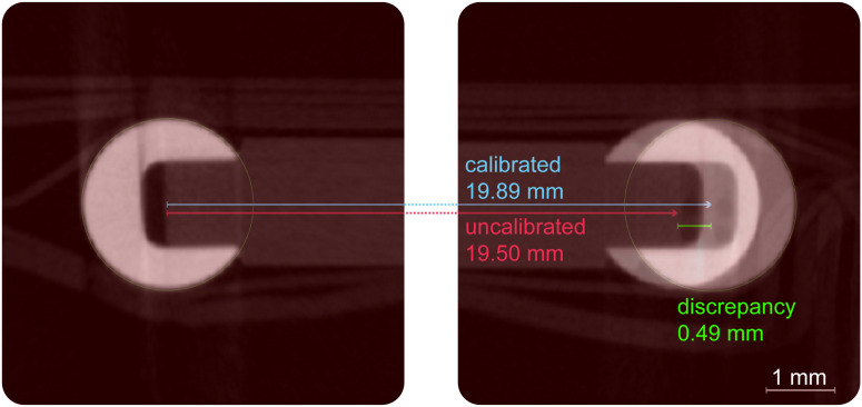
This study aims to evaluate the measurement accuracy of computed tomography (CT) systems, focusing on the necessity of using calibration phantoms for enhanced precision. Both clinical CT and micro-CT systems were evaluated using a specially designed two-ball phantom, which provides a reliable reference for spatial resolution and geometric accuracy. The study involved scanning the phantom with two micro-CT devices (the oversize micro-CT SkyScan 1173 and the high-resolution micro-CT SkyScan 1272) and a clinical CT device, a third-generation dual-source CT scanner (SOMATOM Force), measuring the distance between the centres of two ruby balls. The results showed significant differences in measurement accuracy between the devices. The high-resolution micro-CT provided the most consistent measurements with minimal variance, indicating its superiority in applications requiring high precision. In contrast, the oversize micro-CT exhibited larger errors, particularly at smaller voxel sizes, suggesting that internal calibration affected its accuracy. The dual source CT system had the smallest mean error but a larger standard deviation, indicating less consistency compared to micro-CT systems. Calibration with the two-ball phantom improved measurement accuracy across all devices. This improvement underscores the importance of using calibration phantoms to ensure accurate measurements, especially in fields that require high precision, such as clinical diagnostics and materials science. We concluded that routine calibration with phantoms is essential to achieve high measurement accuracy in CT imaging, thereby increasing the reliability of CT-based analyses in various disciplines.


Conflict of interest statement

The authors have declared that no competing interests exist.

Figures

Fig 1
Fig 1. Two-ball phantom for CT calibration.
(A) 3D rendering and (B) schematic image of a two-ball phantom. (C) For calibration purposes, the distance between the centre of the balls is used, as the outer edge may appear smaller or larger depending on the windowing in the image reconstruction (black arrows). The distance between the two spheres can be measured in 2D (D) or in 3D using matching spheres (E).
Fig 2
Fig 2. Measurement of phantom distance.
CT scans of a calibrated 19.89221 mm (±0.0008 mm) two-ball phantom (blue line) were analysed in (A) 2D cross-sections and (B) 3D volume renderings and shown as violin plots (median, quartiles and distribution). Scans taken with the oversize micro-CT were below the correct phantom length and scans taken with the high-resolution micro-CT were above the correct phantom length. Dual-source CT scans were analysed in the sagittal plane in addition to the coronal plane.
Fig 3
Fig 3. Corrected measurements of phantom distance after calibration.
Measurement results after adjustment of the mean values to the size of the calibrated two-ball phantom of 19.89221 mm (blue line) in (A) 2D cross-sections and (B) 3D volume renderings. The corrected results show a good representation of the actual phantom size. Measurement of scans taken with the SOMATOM Force showed a greater scatter of data compared to the micro-CTs.
Fig 4
Fig 4. Visual comparison of uncalibrated and calibrated measurements.
An overlay on a 2D slice from the oversize micro-CT shows the uncalibrated measured distance (red line and overlay), which is visibly shorter than the actual center-to-center distance. After applying the correction factor derived from the phantom, the calibrated measurement (blue line) accurately aligns with the centers of the two ruby spheres, demonstrating the effectiveness of the calibration.
Fig 5
Fig 5. Phantom edge profile curves.
A profile line of 50 pixels (25 pixels for SOMATOM Force scans) was placed over the outer edge of the ruby ball in each CT scan in the 2D view to determine the gradient of the grey values. (A) The slope of the fit curves (Rodbard fit) with a grey value between 60 and 140 (grey box) was determined for the profile lines and shown as an example for a scan in the high-resolution micro-CT (11 µm voxel size, central position) in red and the oversize micro-CT (20 µm voxel size, central position) in green. (B) Comparison of the slope of the profile lines (B). In the micro-CTs, scans with smaller voxel sizes have steeper profile lines. The steepest profile lines were measured in the high-resolution micro-CT scans.
Fig 6
Fig 6. Exemplary CT scans cropped to one ruby ball.
A cross-sectional view of the top ruby sphere of the phantom is presented in the 2D view with differing scan parameters (left) and the corresponding FFT conversion (right). Positions and voxel sizes were varied. For better interpretation, a computer-generated virtual phantom was added as an idealized reference case (bottom right image pair). This virtual image was created with a defined, slight blur at the edge to serve as a benchmark. The FFT of this virtual phantom produces a characteristic checkered pattern, which serves as a reference for how a blurred edge is represented in the frequency domain. In comparison, the FFTs of the real scans with larger voxel sizes (e.g., 23 µm) and consequently lower edge sharpness show ring-shaped gradations, indicating greater image blur. Scale: 3 mm.

References

    1. Khoury BM, Bigelow EMR, Smith LM, Schlecht SH, Scheller EL, Andarawis-Puri N, et al. The use of nano-computed tomography to enhance musculoskeletal research. Connect Tissue Res. 2015;56(2):106–19. doi: 10.3109/03008207.2015.1005211 - DOI - PMC - PubMed
    1. Renders GAP, Mulder L, Lin AS, Langenbach GEJ, Koolstra JH, Guldberg RE, et al. Contrast-enhanced microCT (EPIC-μCT) ex vivo applied to the mouse and human jaw joint. Dentomaxillofac Radiol. 2014;43(2):20130098. doi: 10.1259/dmfr.20130098 - DOI - PMC - PubMed
    1. Kerckhofs G, Sainz J, Wevers M, Van de Putte T, Schrooten J. Contrast-enhanced nanofocus computed tomography images the cartilage subtissue architecture in three dimensions. Eur Cell Mater. 2013;25:179–89. doi: 10.22203/ecm.v025a13 - DOI - PubMed
    1. Bouxsein ML, Boyd SK, Christiansen BA, Guldberg RE, Jepsen KJ, Müller R. Guidelines for assessment of bone microstructure in rodents using micro-computed tomography. J Bone Miner Res. 2010;25(7):1468–86. doi: 10.1002/jbmr.141 - DOI - PubMed
    1. Sasov A, Liu X, Salmon PL. Compensation of mechanical inaccuracies in micro-CT and nano-CT. In: Stock SR, editor. Developments in X-Ray Tomography VI. SPIE; 2008. p. 70781C.

MeSH terms