. 2025 Sep 24;12(9):242229.
doi: 10.1098/rsos.242229. eCollection 2025 Sep.

GrowCAD: bioinspired mathematical design for additive manufacturing

Affiliations

GrowCAD: bioinspired mathematical design for additive manufacturing

Nasim Mahmoodi et al. R Soc Open Sci. .

Abstract

While the socioeconomic and environmental benefits of additive manufacturing (AM) are acknowledged, design for AM remains a perpetual challenge in the wider implementation of the technique. Design in the context of AM is an interconnected and broad topic. It encompasses not only function and form, but also how geometry is represented digitally, the associated software and human problem-solving capabilities within the geometric opportunities and constraints. This research focuses on enhancing human knowledge and creativity within the bounds of an ever-evolving design space, encompassing digital and human capabilities. A bioinspired methodology is introduced, drawing an analogy between plant growth and the layer-by-layer AM process. This results in the development of a novel length-polar-projection coordinate system, and the associated algebraic definition of centre lines and cross-sections. This mathematical representation of geometry forms the foundation of the design framework, GrowCADTM. Retaining the algebraic format of the geometry enables a manufacturability analysis, parametric editability and computer-aided design compatibility. The research is validated through qualitative analysis of the shape fidelity and efficiency, the ability to detect non-manufacturable geometry, the end-to-end functionality and the printability of the successful geometries. The simplicity and intuitive nature of GrowCADTM offer a method by which to enhance the engineer's knowledge and creativity.

Keywords: 3D printing; additive manufacturing; bioinspired; engineering design; mathematical biology.


Conflict of interest statement

We declare we have no competing interests.

Figures

A parametrically defined upscaled structure which will twist and bend in response to changes in the cross-sectional properties
Figure 1.
A parametrically defined upscaled structure which will twist and bend in response to changes in the cross-sectional properties, where T, N, L, R and s represent unit tangent to the curve, unit normal to the curve, axial length, cross-sectional radii and arclength parameter, respectively (modified from [37]).
Example construction lines and planes with or without the TNB algorithm to ensure that cross-sections are well-defined at every point and do not reorient abruptly
Figure 2.
Example construction lines and planes with or without the TNB algorithm to ensure that cross-sections are well defined at every point and do not reorient abruptly. (A) Using the standard normal vector as the reference direction leads to undefined and/or abruptly reorienting cross-sections. On this construction line, there are three construction points where the local curvature is zero. At these points, the normal vector is undefined; hence, the absence of cross-sections. Moreover, as this line passes through its mid-point, the normal vector flips its direction; hence the abrupt reorientation (by 180°) of cross-sections. (B) Using the TNB alignment algorithm, all reference directions are well defined and do not reorient abruptly from one construction point to the next.
Example construction lines and planes demonstrating the TNB and XYZ alignment algorithms
Figure 3.
Example construction lines and planes demonstrating the TNB and XYZ alignment algorithms. Given a construction line that bends out of the plane (by twisting around the z-axis), the two alignment methods described in §3.2 yield different default behaviours. (A) The TNB method provides cross-sections that rotate with the twisting of the construction line, by fixing the direction of alignment with respect to an internal frame of reference which reorients along the line. (B) The XYZ method fixes the direction of alignment with respect to the external Cartesian frame of reference.
(A) interface workflow of GrowCADTM with Fusion 360.
Figure 4.
(A) Interface workflow of GrowCADTM with Fusion 360. (B) Non-guided and guided lofted 3D structure examples. (C) 3D construction using XYZ alignment with guided-rail loft.
Comparison in computational process to develop a CAD file using GrowCADTM and Fusion 360
Figure 5.
Comparison in computational process to develop a CAD file using GrowCADTM and Fusion 360.
Three-dimensional printed representative models for experiment ‘P2’ to design and manufacture various models through using different (a)
Figure 6.
Three-dimensional printed representative models for experiment P2 to design and manufacture various models through using different (A) construction line: off-axis single helix (P2-1-1), out-of-plane 2D wave (P2-1-2), on-axis double helix construction line (P2-1-3), and (B) cross-section by varying its size (P2-2-1), shape (P2-2-2), rotation (P2-2-3), size, shape and rotation simultaneously (P2-2-4).
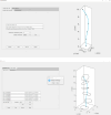
Two screenshots of the GrowCAD user interface
Figure 7.
Two screenshots of the GrowCADTM user interface. Top: the ‘Construction Line’ screen, using the novel LPP system (§3.1) to specify a curve in 3D space. The values shown, and the construction line and points generated, are built-in defaults, while the input fields allow user customizations. Bottom: the ‘Cross-sections’ screen, allowing custom designs of non-axisymmetric cross-sections at the construction points under either the TNB or the XYZ alignment mode, with user-specified rotation and tilt angles (§3.2). The dropdown menu ‘Examples’ contains mathematical expressions for various shapes (‘hearts’ are shown here). An analysis of wall thickness is carried out on the cross-sectional boundaries (§3.3.1) and proceeding to ‘analyse overhang’ through the pop-up dialogue initiates an analysis of overhang angles on the extrapolated surface (§3.3.2), which produces results such as those in table 3.
Figure 8.
Figure 8.
Additional perspectives of 3D printed representative models for experiment P2 to design and manufacture various models through using different (top) construction line: off-axis single helix (P2-1-1), out-of-plane 2D wave (P2-1-2), on-axis double helix construction line (P2-1-3), and (bottom) cross-section by varying its size (P2-2-1), shape (P2-2-2), rotation (P2-2-3), size, shape and rotation simultaneously (P2-2-4).

References

    1. Hettiarachchi BD, Brandenburg M, Seuring S. 2022. Connecting additive manufacturing to circular economy implementation strategies: links, contingencies and causal loops. Int. J. Prod. Econ. 246, 108414. ( 10.1016/j.ijpe.2022.108414) - DOI
    1. Mehrpouya M, Dehghanghadikolaei A, Fotovvati B, Vosooghnia A, Emamian SS, Gisario A. 2019. The potential of additive manufacturing in the smart factory industrial 4.0: a review. Appl. Sci. 9, 3865. ( 10.3390/app9183865) - DOI
    1. Minshall T, Featherston C. 2019. A case study of the development of the UK’s additive manufacturing national strategy 2014-2017. University of Cambridge repository. ( 10.17863/CAM.35689) - DOI
    1. Pradel P, Zhu Z, Bibb R, Moultrie J. 2018. A framework for mapping design for additive manufacturing knowledge for industrial and product design. J. Eng. Des. 29, 291–326. ( 10.1080/09544828.2018.1483011) - DOI
    1. Ashby MF, Johnson K. 2013. Materials and design: the art and science of material selection in product design. Oxford, UK: Butterworth-Heinemann.

LinkOut - more resources