. 2025;4(1):41.
doi: 10.1007/s44245-025-00130-6. Epub 2025 Sep 29.

Hydrodynamic lubrication effects in textured PEEK surfaces for friction reduction

Affiliations

Hydrodynamic lubrication effects in textured PEEK surfaces for friction reduction

Christopher W Harris et al. Discov Mech Eng. 2025.

Abstract

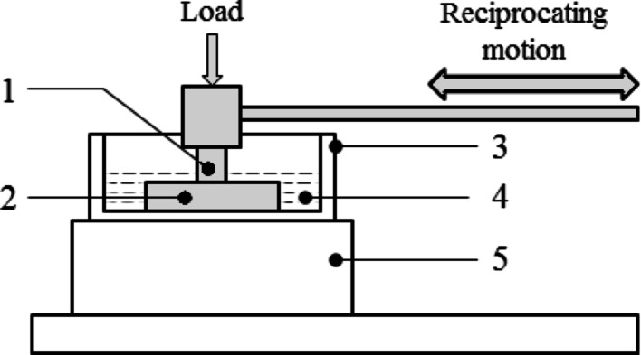
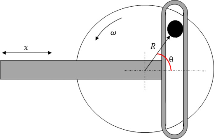
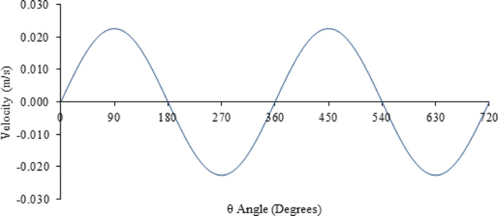
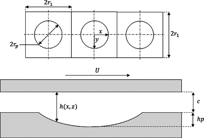
The tribology of dimple-shaped textures is investigated within a reciprocating polymeric sliding couple of Invibio poly-ether-ether-ketone (grade 450G). A novel theoretical model was developed for this aim, describing hydrodynamic pressure and frictional force due to surface modifications. Experiments show reduced friction across all textures compared to un-textured surfaces. The parameters of texture depth (5-20 µm) and diameter (50-200 µm) were isolated to analyse the effect of each independently. The diameter showed good agreement with the model; however, depth showed variation at the extremities of the parameters examined. The experimental friction force captured over a single stroke was compared to the instantaneous theoretical friction force, and good agreement was found in the form of the friction trace within the hydrodynamic region of a reciprocating stroke. The texture parameter combination of 50 µm diameter and 20 µm depth showed the most significant reduction in friction at 48.7%.

Keywords: Bearing; Friction; PEEK; Surface textures; Water lubrication.


Conflict of interest statement

Competing interestsThe authors declare no competing interests.

Figures

Fig. 1
Fig. 1
Schematic of the Lower Specimen (flat plate, PEEK) and upper specimen (cylindrical pin, PEEK). a 60 mm, b 4 mm, c 25 mm, d 8 mm diameter, e 20 mm, f 5 mm
Fig. 2
Fig. 2
a Representative image of 50 µm diameter texture dispersed over the surface at a density of 20%. b Profile image of 50 µm texture with a depth of 20 µm
Fig. 3
Fig. 3
Experimental layout of TE77 tribometer. (1) upper specimen (un-textured) (2) lower specimen (textured/un-textured), (3) lubricant bath, (4) lubricant (reagent grade purified water), (5) heater block
Fig. 4
Fig. 4
The variation of average COF with changing surface parameters—diameter and depth—for a PEEK frictional Couple. Sliding at a reciprocating frequency of 1 Hz under a load of 75N in water-lubricated conditions maintained at a temperature of 37 °C
Fig. 5
Fig. 5
3D plot of the regression model, showing the effect of diameter and depth combinations has upon the average coefficient of friction
Fig. 6
Fig. 6
Model schematic and coordinate scheme of two conformal surfaces separated by a thin film of lubricant, c. The upper surface travels at a reciprocating velocity, U, and the lower surface is fixed. An applied load, FL is opposed by a force deriving from hydrodynamic pressure, FP
Fig. 7
Fig. 7
The schematic of the Scotch yoke mechanism
Fig. 8
Fig. 8
Velocity profile produced by a scotch yoke mechanism with a radius R equivalent to the experimental stroke length, rotating at 60 RPM over a time scale of 2 s. The example illustrates 2 complete rotations (720°) corresponding to 4 strokes contained within 2 reciprocating cycles
Fig. 9
Fig. 9
Surface geometry and notation. Plan view of 3 consecutive textures indicating texture cell length (2r1), texture diameter (2rp), and coordinate scheme. The bottom figure shows a cross-section across one textured cell separated by an initial gap, c. Where h (x,z) is the instantaneous film thickness and hp is the depth of the textured pore
Fig. 10
Fig. 10
Flowchart identifying the computation procedure to determine the force between applied load and hydrodynamic pressure through to the calculation of friction with the specified surface texture parameters
Fig. 11
Fig. 11
dimensionless pressure distribution within one reciprocating stroke across three consecutive textures with a diameter of 50 µm and depth of 10 µm
Fig. 12
Fig. 12
Hydrodynamic pressure distribution plotted over 1 reciprocating stroke moving at velocity (v) across 3 consecutive textured pores with dimensions of 50 µm diameter and a depth of 10 µm
Fig. 13
Fig. 13
Friction force and Stroke length vs. Sliding time for a control (un-textured) and a textured surface. Friction data captured at 100 Hz over 2 s. Tests were conducted at 1 Hz reciprocating frequency, a load of 50N with water lubrication maintained at 37 °C
Fig. 14
Fig. 14
Experimental friction force for a textured surface vs the analytically modelled instantaneous friction force for a textured surface of 100 µm diameter and 10 µm depth. The plot highlights the three regions of tribological activity expected within a reciprocating contact where Region A: Boundary/mixed lubrication, Region B: Hydrodynamic and squeeze film lubrication, and Region C: Mixed/boundary lubrication
Fig. 15
Fig. 15
Comparing the standardized friction force for the theoretical and experimental model at various depths in the range from 50 to 200 µm at 25 µm intervals
Fig. 16
Fig. 16
Comparing the standardized friction force for the theoretical and experimental models at various depths in the range from 5 to 20 µm at 2.5 µm intervals
Fig. 17
Fig. 17
Contour plot and corresponding colour bar expressing the level of variation in β between experimental and theoretical models. The variation is measured by comparing all texture parameter combinations indicated on the depth and diameter axis. The level of variation displayed corresponds to the colour bar on the right of the figure

References

    1. Ingham E, Fisher J. The role of macrophages in osteolysis of total joint replacement. Biomaterials. 2005;26:1271–86. 10.1016/j.biomaterials.2004.04.035. - PubMed
    1. Zeh A, Planert M, Siegert G, Lattke P, Held A, Hein W. Release of cobalt and chromium ions into the serum following implantation of the metal-on-metal maverick-type artificial lumbar disc (Medtronic Sofamor Danek). Spine. 2007;32(3):348–52. - PubMed
    1. Delaunay C, Petit I, Learmonth ID, Oger P, Vendittoli PA. Metal-on-metal bearings total hip arthroplasty: the cobalt and chromium ions release concern ଝ. Orthop Traumatol Surg Res. 2010;96(8):894–904. 10.1016/j.otsr.2010.05.008. - PubMed
    1. De Aza AH, Chevalier J, Fantozzi G, Schehl M, Torrecillas R. Crack growth resistance of alumina, zirconia and zirconia toughened alumina ceramics for joint prostheses. Biomateerials. 2002;23:937–45. 10.1016/S0142-9612(01)00206-X. - PubMed
    1. Bal BS, Garino JP, Ries MD. Ceramics for prosthetic hip and knee joint replacement. J Am Ceram Soc. 1988;22642:2007. 10.1111/j.1551-2916.2007.01725.x.