. 2025 Sep 17:6:1654118.
doi: 10.3389/fdmed.2025.1654118. eCollection 2025.

An integrated approach to tracking mandibular position relative to incisal and condylar envelopes of motion during intraoral clinical procedures: a new look at TMJ movements

Affiliations

An integrated approach to tracking mandibular position relative to incisal and condylar envelopes of motion during intraoral clinical procedures: a new look at TMJ movements

Jing-Sheng Li et al. Front Dent Med. .

Abstract

Current methods for tracking temporomandibular joint (TMJ) movements are difficult to perform during dental procedures. Yet precise and accurate quantification of mandibular movements is critical for understanding temporomandibular biomechanics and how certain movements may contribute to temporomandibular dysfunction. This is particularly relevant to clinical procedures that might move the mandible near or beyond its functional range of motion. We present a novel approach that integrates cone-beam computed tomography, optical intra-oral scans, and six degree-of-freedom electromagnetic sensor data to quantify mandibular movements. This method employs rigid body transformations to generate subject-specific three-dimensional (3D) envelopes of motion and assess whether incisal and condylar landmarks remain within their functional 3D envelopes of motion. We demonstrate the clinical utility of this approach through simulated mandibular poses presented relative to the limits of incisal and condylar envelopes created from that individual's voluntary border movements. Our findings reveal that condylar or incisal points in simulated mandibular poses are located beyond their normal motion envelopes, highlighting the importance of simultaneous monitoring of incisal and condylar landmarks. This methodology provides a clinically relevant tool for understanding temporomandibular biomechanics and it has the potential to signal clinicians when jaw movements during dental and oral surgical procedures approach or exceed the jaw's functional range of motion and such corrective feedback could prevent adverse effects on the TMJ.

Keywords: TMD; TMJ; dental procedure; envelope of motion; imaging; kinematics; oral surgery.


Conflict of interest statement

The authors declare that the research was conducted in the absence of any commercial or financial relationships that could be construed as a potential conflict of interest.

Figures

Figure 1
Figure 1
Sensor-embedded retainer for kinematic tracking. (A) Cone-beam computed tomography (CBCT) and intraoral scans (IOS). (B) CBCT and IOS were registered to create high-resolution fused-CBCT (f-CBCT). (C) 3D printed f-CBCT model as a mold for retainer creation. (D) Use dental vacuum forming machine to make sensor­embedded retainer. (E) Use dental points to locate microsensors in 3D space.
Figure 2
Figure 2
Schematic illustration of incisal trajectories (black solid lines). The participant uses this figure as a guide to move the jaw to different levels of mouth opening (MO) starting from MIP position or protruded position.
Figure 3
Figure 3
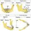
The subject-specific incisal envelope of movements is shown in the frontal plane (A), sagittal plane (B), transverse plane (C), and in 3D (D) relative to the incisors. A bounding box for the incisal envelope was created to measure the dimensions of the envelope.
Figure 4
Figure 4
The subject-specific condylar envelope of movements is shown in the frontal plane (A,C), in 3D (B), and sagittal plane (D,E) relative to the high-point of the condyle. A bounding box for the condylar envelope was created to measure the dimensions of the envelope.
Figure 5
Figure 5
Approach used to identify sensor signal distortion. (A) Distance between mandibular sensors over time while a metal tongue retractor was placed and removed. (B) Distance between a specific cranial sensor (CS) and the left and right mandibular microsensors (MS). Scenario 1 shows a period of reliable signal from frames from 1–600, around frames 900–1,500, deflections occur which indicate the presence of artifacts. Portions of the data show distortion of only one microsensor (scenario 2) or both microsensors (scenario 3).
Figure 6
Figure 6
Simulation case 1. (A) Right condylar points at maximum opening (black) and simulated pose (red) are shown relative to condylar envelope. (B) lncisal and condylar points relative to their envelopes, shown at full mouth opening (transparent jaw) vs. 110% of mouth opening along a circular path. (C), As in (A), but shown for left condyle. (D,E) Frontal and sagittal views show incisal points relative to its envelope.
Figure 7
Figure 7
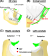
Simulation case 2. (A) Two condylar points were used to create a rotational axis for simulating a 40-mm mouth opening. (B) Simulated incisal point is shown outside the incisal envelope of movement. (C,D) Condylar points at simulated pose remain unchanged.
Figure 8
Figure 8
Simulation case 3. (A) Right condyle positions at 50% mouth opening to the rightmost border and simulated pose are shown relative to condylar envelope. (B) Illustration of a 3 mm incisal displacement to the right of the border of incisal envelope. lncisal and condylar points relative to their envelopes, shown at 50% opening with displacement to the rightmost border (transparent jaw) and simulated pose. (C) As in (A), but shown for left condyle. (D,E) Frontal and sagittal views show incisal point at 50% opening with displacement to the rightmost of the border and simulated pose relative to its envelope.
Figure 9
Figure 9
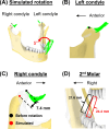
Simulation case 4. (A) The mandible is rotated for 5° around the axis connecting incisor and left condyle. (B) Left condylar point remains unchanged. (C) In this simulated pose, the right condyle was displaced by 7.4 mm. (D) The distance between the upper and lower second molars increased.

References

    1. National Institute of Dental and Craniofacial Research. Prevalence of TMJD and its Signs and Symptoms (2018). Available online at: https://www.nidcr.nih.gov/research/data-statistics/facial-pain/prevalence (Accessed August 20, 2024).
    1. National Academies of Sciences E and M. Temporomandibular disorders: priorities for research and care. In: Bond EC, Mackey S, English R, Liverman CT, Yost O, editors. Temporomandibular Disorders: Priorities for Research and Care. Washington, DC: The National Academies Press; (2020). p. 1–3. Available online at: https://nap.nationalacademies.org/catalog/25652/temporomandibular-disord... (Accessed August 20, 2024). - PubMed
    1. Kapos FP, Exposto FG, Oyarzo JF, Durham J. Temporomandibular disorders: a review of current concepts in aetiology, diagnosis and management. Oral Surg. (2020) 13(4):321–34. 10.1111/ors.12473 - DOI - PMC - PubMed
    1. Huang GJ, LeResche L, Critchlow CW, Martin MD, Drangsholt MT. Risk factors for diagnostic subgroups of painful temporomandibular disorders (TMD). J Dent Res. (2002) 81(4):284–8. 10.1177/154405910208100412 - DOI - PubMed
    1. Sharma S, Wactawski-Wende J, Lamonte MJ, Zhao J, Slade GD, Bair E, et al. Incident injury is strongly associated with subsequent incident temporomandibular disorder: results from the OPPERA study. Pain. (2019) 160(7):1551–61. 10.1097/j.pain.0000000000001554 - DOI - PMC - PubMed

LinkOut - more resources