. 2025 Dec;24(6):2195-2215.
doi: 10.1007/s10237-025-02013-x. Epub 2025 Oct 3.

An MRI-derived head-neck finite element model

Affiliations

An MRI-derived head-neck finite element model

Hossein Bahreinizad et al. Biomech Model Mechanobiol. 2025 Dec.

Abstract

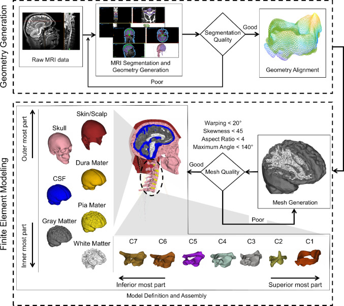
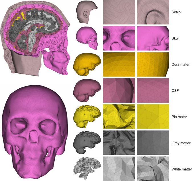
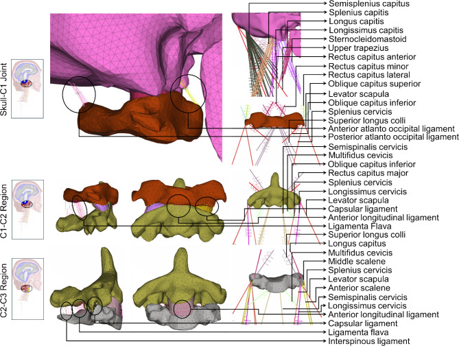
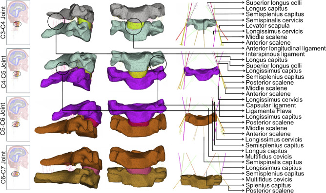
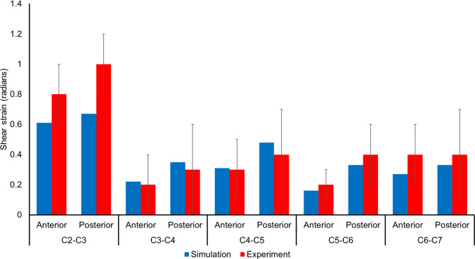
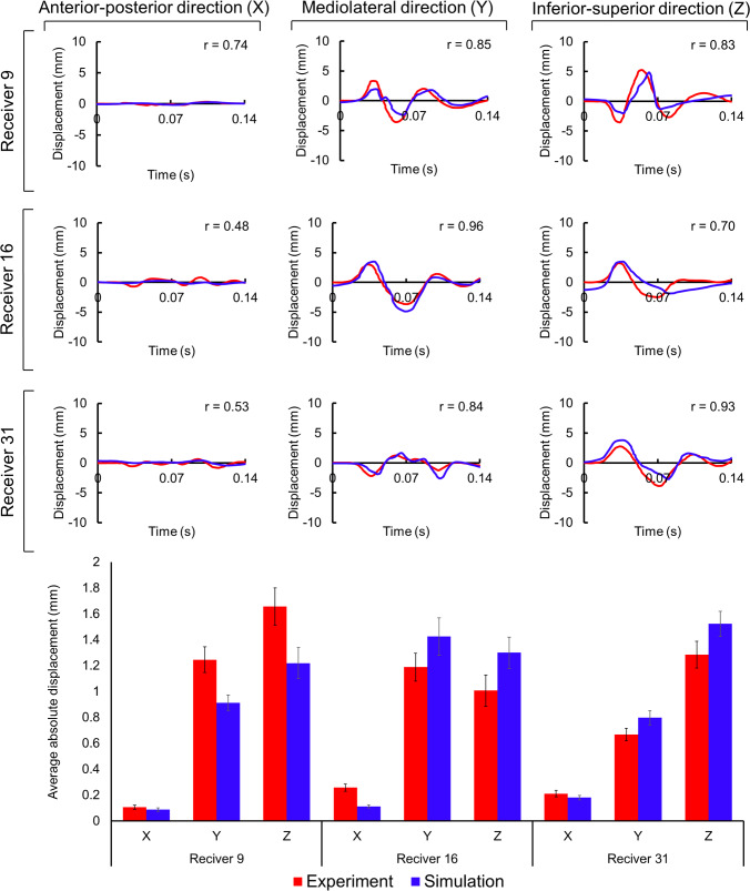
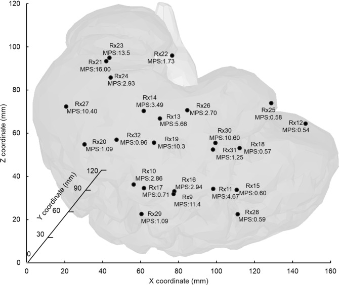
This study aimed to develop and validate a magnetic resonance imaging (MRI)-derived biofidelic head-neck finite element (FE) model comprised of scalp, skull, CSF, brain, dura mater, pia mater, cervical vertebrae, and disks, 14 ligaments, and 42 neck muscles. We developed this model using head and neck MRI images of a healthy male participant and by implementing a novel brain hexahedral meshing algorithm and a scalp erosion model. The model was validated by replicating three experimental studies: Alshareef's brain sonomicrometry study, NBDL's high-acceleration profile, and Ito's frontal impact cervical vertebrae study. The results also showed that the segmented geometries of the model aligned closely with the literature data (within 3 σ limit). The brain displacement results of the model aligned well (r = 0.48-0.96) with those reported in Alshareef's experimental study. The head-neck kinematic responses of the model showed a strong correlation (r > 0.97) with the NBDL's experimental results. The simulation of Ito's experimental condition yielded peak shear strain values of the cervical spine within 1 σ of the experimental data. Our developed head-neck FE model provides an effective computational platform for advancing brain and head injury biomechanics research and evaluating protective equipment in various impact scenarios.

Keywords: Computational biomechanics; Finite element method; Image processing; Neck contribution; Simulation and modeling; Traumatic brain injury.


Conflict of interest statement

Declarations. Conflict of interest: The authors declare no conflict of interest.

Figures

Fig. 1
Fig. 1
A schematic presentation of the methodological framework. The framework follows four consecutive steps: (1) 3D head-neck geometry development from a magnetic resonance imaging (MRI) dataset, (2) Geometrical verification of developed images, (3) Finite Element (FE) meshing of the model geometries, and (4) defining material properties. The steps for generating and verifying head-neck geometry are outlined in the top dashed box, and the steps for finite element modeling are provided in the bottom dashed box. Anatomical segmentation quality was assessed by comparing the geometrical dimensions of segmented components with literature-reported data, in addition to a visual inspection with respect to the subject’s raw MRI data
Fig. 2
Fig. 2
An exploded view of the head finite element model displays the schematics of the mesh structures of scalp, skull, dura mater, CSF, pia mater, brain’s gray matter, and brain’s white matter
Fig. 3
Fig. 3
An exploded view of the upper neck finite element model to display the schematics of the mesh structures of the skull, C1, C2, C3, C2-C3 disk, cervical muscles, and ligaments from the skull to the C3. The included cervical muscles are obliquus capitis superior, superior longus colli, rectus capitus major, rectus capitus minor, longus capitis, rectus capitis ant, rectus capitis lat, anterior scalene, middle scalene, posterior scalene, sternocleidomastoid, longissimus capitis, longissimus cervicis, multifidus cervicis, semisplenius capitus, semispinalis cervicis, splenius capitis, splenius cervicis, levator scapula, oblique capitus inferior, and trapezius. The included ligaments are anterior longitudinal ligament, posterior longitudinal ligament, ligamentum flavum, capsular ligament, interspinous ligaments, tectorial membrane, anterior and posterior atlanto-occipital ligaments, anterior and posterior atlanto-axial ligaments, apical ligament, alars ligament, transverse ligament, and cruciate ligament of atlas
Fig. 4
Fig. 4
An exploded view of the middle and lower neck finite element model to display the schematics of the mesh structures of C3, C4, C5, C6, and C7 vertebrae, C3-C4, C4-C5, C5-C6, and C6-C7 disks, cervical muscles, and ligaments from C3 to C7. The included cervical muscles are obliquus capitis superior, superior longus colli, rectus capitus major, rectus capitus minor, longus capitis, rectus capitis ant, rectus capitis lat, anterior scalene, middle scalene, posterior scalene, sternocleidomastoid, longissimus capitis, longissimus cervicis, multifidus cervicis, semisplenius capitus, semispinalis cervicis, splenius capitis, splenius cervicis, levator scapula, oblique capitus inferior, and trapezius. The included ligaments are the anterior longitudinal ligament, posterior longitudinal ligament, ligamentum flavum, capsular ligament, interspinous ligaments, tectorial membrane, anterior and posterior atlanto-occipital ligaments, anterior and posterior atlanto-axial ligaments, apical ligament, alars ligament, transverse ligament, and cruciate ligament of atlas
Fig. 5
Fig. 5
Schematic illustration of the tetrahedral to hexahedral (tet-to-hex) conversion process used for brain and CSF meshing. The top row shows a 2D representation of the method: (1) original tetrahedral cross-section; (2) subdivision using midpoints of edges and faces (highlighted in red); (3) resulting 2D hexahedral-like elements. The bottom row shows the corresponding 3D implementation: (1) original tetrahedral element; (2) edge and face subdivision (red lines); (3) resulting 3D hexahedral elements
Fig. 6
Fig. 6
Experimental impact scenarios that were numerically replicated in this study: a linear acceleration profile of NBDL study (Ewing and Thomas 1972) with respect to T1 vertebral rotation (Thunnissen et al. 1995), and b linear acceleration profile for Ito’s (Ito et al. 2005) cervical vertebrae study, and c Angular velocity profile for Alshareef‘s (Alshareef et al. 2018) sonomicrometry study. The run time for finite element simulations of NBDL, Ito’s, and Alshareef’s studies were, respectively, 220 ms, 350 ms, and 150 ms
Fig. 7
Fig. 7
Comparison between model-predicted and NBDL-experimental neck flexion angles for the complete simulation duration (top) and a visual comparison between model-prediction (top) and experimental head-neck kinematic responses (bottom) at three different time instances (Thunnissen et al. 1995). The shaded area represents the experimental range of neck angles, while the solid line indicates the corresponding simulation results
Fig. 8
Fig. 8
Comparison between simulated and experimental (mean ± SD) peak shear strain (Ito et al. 2005) in an 8 g frontal impact Scenario
Fig. 9
Fig. 9
Comparative analysis of brain displacement between simulated and experimental results (Alshareef et al. 2018) in X, Y, and Z directions across three receiver locations. Corresponding correlation coefficients (r) are included for each case. Comparison of simulated average absolute displacement values with experimental counterparts (mean ± SD)
Fig. 10
Fig. 10
A sagittal view of the 3D brain model with the approximate locations of all 24 receivers. The peak maximum principal strain (MPS) values of all receivers are in percentage (%). The peak MPS for the overall brain was 40.20%

References

    1. Alshareef A, Giudice JS, Forman J, Salzar RS, Panzer MB (2018) A novel method for quantifying human in situ whole brain deformation under rotational loading using sonomicrometry. J Neurotrauma 35:780–789 - PubMed
    1. Anderst WJ, Donaldson WF III, Lee JY, Kang JD (2015) Three-dimensional intervertebral kinematics in the healthy young adult cervical spine during dynamic functional loading. J Biomech 48:1286–1293 - PubMed
    1. Babiloni F, Babiloni C, Carducci F, Del Gaudio M, Onorati P, Urbano A (1997) A high resolution EEG method based on the correction of the surface Laplacian estimate for the subject’s variable scalp thickness. Electroencephalogr Clin Neurophysiol 103:486–492 - PubMed
    1. Barker JB, Cronin DS (2021) Multilevel validation of a male neck finite element model with active musculature. J Biomech Eng 143:011004 - PubMed
    1. Bayly PV et al (2021) MR imaging of human brain mechanics in vivo: new measurements to facilitate the development of computational models of brain injury. Ann Biomed Eng 49:2677–2692 - PMC - PubMed

LinkOut - more resources