. 2025 Sep 17:24:e00704.
doi: 10.1016/j.ohx.2025.e00704. eCollection 2025 Dec.

Development of a low-cost electrospinning system with a bidirectional collector for uniform nanofibrous membranes

Affiliations

Development of a low-cost electrospinning system with a bidirectional collector for uniform nanofibrous membranes

Jhonatan A Gutierrez-Rivera et al. HardwareX. .

Abstract

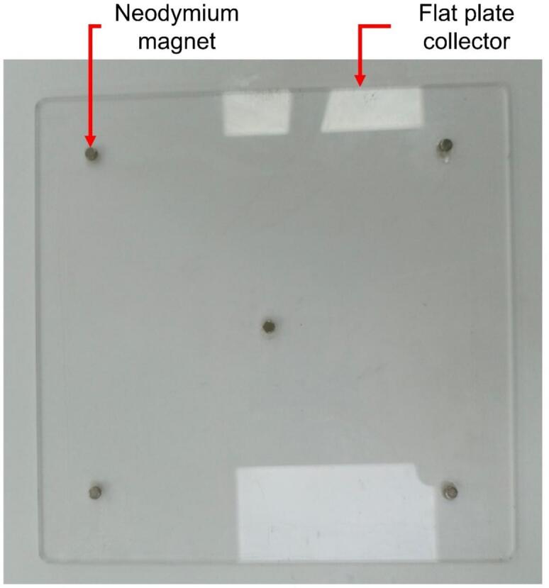
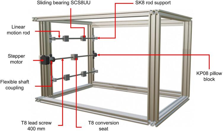
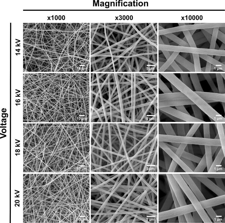
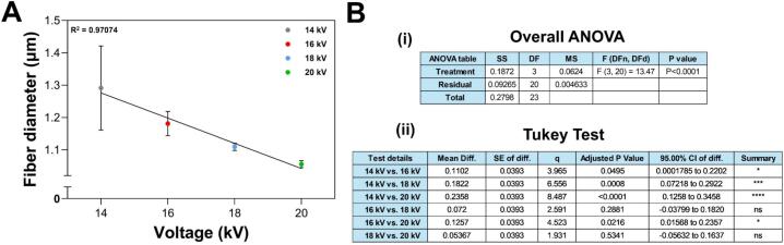
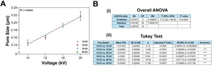
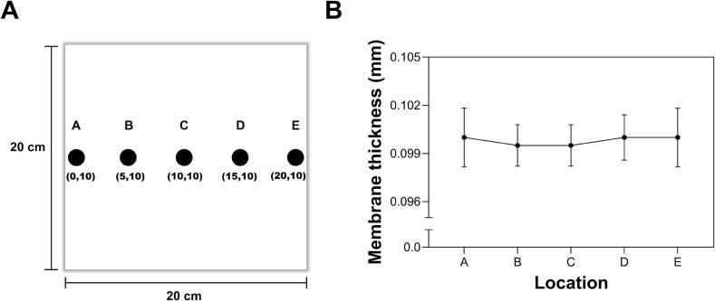
The electrospinning process is a widely used technique for the fabrication of membranes with nanometric fibers, employing polymeric materials such as polyvinylidene fluoride and polycaprolactone. The shape of the fiber collector, whether static or rotating, significantly impacts membrane uniformity. Although rotating drum collectors are the most used, they exhibit drawbacks such as uneven fiber accumulation. Current solutions, which favor rotating over static collectors, tend to be more expensive and complex. This article presents an electrospinning setup that utilizes a flat acrylic plate with bidirectional movement along the X and Y axes, enhancing fiber collection and membrane uniformity. This design improves process efficiency, fiber reproducibility, and system scalability. Polystyrene electrospun nanofibrous membranes were fabricated, and their average fiber diameter and pore size were analyzed, demonstrating the system's capability to produce micro- and nanometric fibers.

Keywords: Electrospinning; Flat plate; Nanomembranes; Polymeric materials; Polystyrene.


Conflict of interest statement

The authors declare that they have no known competing financial interests or personal relationships that could have appeared to influence the work reported in this paper.

Figures

None
Graphical abstract
Fig. 1
Fig. 1
Main parts of the electrospinning equipment.
Fig. 2
Fig. 2
Collector flat plate.
Fig. 3
Fig. 3
High voltage power supply: A) Front view. B) Left side view. C) Right side view.
Fig. 4
Fig. 4
Syringe pump.
Fig. 5
Fig. 5
Graphic interface of the UGS program.
Fig. 6
Fig. 6
Operation of the control module.
Fig. 7
Fig. 7
Structure of the protective enclosure.
Fig. 8
Fig. 8
Components of the linear motion kit.
Fig. 9
Fig. 9
300 mm linear motion kit for vertical displacement.
Fig. 10
Fig. 10
400 mm linear motion kit for horizontal displacement.
Fig. 11
Fig. 11
Mechanical structure of the collector.
Fig. 12
Fig. 12
Assembly of the 400 mm linear motion guide.
Fig. 13
Fig. 13
Assembly of the 300 mm linear motion guide and collector plate.
Fig. 14
Fig. 14
Assembly process of the pump and its structural base. A) Base plate with two aluminum profiles. B) Addition of small acrylic plate. C) Installation of upper aluminum profiles. D) Mounting plate for syringe pump. E) Pump integration. F) Final assembled support with syringe pump.
Fig. 15
Fig. 15
Electrospinning structure with the attached syringe pump.
Fig. 16
Fig. 16
Electrospinning equipment.
Fig. 17
Fig. 17
Control module of the electrospinning equipment.
Fig. 18
Fig. 18
Electrospinning equipment fully assembled and operational.
Fig. 19
Fig. 19
SEM images of PS-based nanofibers from membranes obtained at various voltages, 14 kV, 16 kV, 18 kV, and 20 kV, and magnifications, x1000, x3000, and x10,000.
Fig. 20
Fig. 20
Fiber diameter variation in each membrane (A) as a function of the applied voltage. (B) Error analysis for fiber diameter: (i) ANOVA and (ii) Tukey test. One-way ANOVA showed that applied voltage significantly affects fiber diameter (F = 13.47, p < 0.0001). Linear regression revealed a strong negative correlation (R2 = 0.97), indicating that increasing voltage results in smaller fibers. The Tukey test showed significant differences among the voltage ranges of 14–16 kV, 14–18 kV, 14–20 kV, and 16–20 kV. In contrast, differences between similar voltage levels, 16–18 kV, and 18–20 kV, were not statistically significant. These results underscore that voltage plays a crucial role in influencing fiber diameter. * p < 0.05, *** p < 0.001, **** p < 0.0001.
Fig. 21
Fig. 21
Contact angle measurements for the membranes obtained at: (A) 14 kV, (B) 16 kV, (C) 18 kV, and (D) 20 kV.
Fig. 22
Fig. 22
Contact angle variation (A) as a function of the applied voltage. (B) Error analysis for contact angle: (i) ANOVA and (ii) Tukey test. One-way ANOVA showed that applied voltage significantly affects the contact angle of the membranes (F = 46.48, p < 0.0001). Additionally, linear regression revealed a strong positive correlation (R2 = 0.98), suggesting that increasing voltage results in a larger contact angle. The Tukey test showed significant differences between all pairs of voltage levels. These results underscore that voltage plays a crucial role in tuning the surface wettability. * p < 0.05, *** p < 0.001, **** p < 0.0001.
Fig. 23
Fig. 23
Pore size variation of the membranes (A) as a function of the applied voltage. (B) Error analysis for pore size: (i) ANOVA and (ii) Tukey test. One-way ANOVA revealed that applied voltage significantly affects pore size (F = 86, p < 0.0001). Linear regression revealed a strong positive correlation (R2 = 0.94), indicating that increasing voltage results in a large pore size. The Tukey test revealed significant differences between all voltage level pairs. These findings highlight the importance of voltage in modulating pore size. * p < 0.05, *** p < 0.001, **** p < 0.0001.
Fig. 24
Fig. 24
Porosity percentage (A) as a function of the applied voltage. (B) Error analysis for porosity: (i) ANOVA and (ii) Tukey test. One-way ANOVA indicated that applied voltage significantly influences membrane porosity (F = 16.67, p < 0.0008). Linear regression demonstrated a strong positive relationship (R2 = 0.99), implying that increasing voltage boosts porosity. The Tukey test showed significant differences between 14–18 kV, 14–20 kV and 16–20 kV, whereas other pairs were not statistically different. These results emphasize voltage as a critical factor in controlling porosity, with the most pronounced differences seen between the lowest and highest voltage levels. * p < 0.05, *** p < 0.001, **** p < 0.0001.
Fig. 25
Fig. 25
Nanofibrous membrane thickness across at (A) different locations on the surface and (B) its values.

References

    1. Han Y., Xu Y., Zhang S., Li T., Ramakrishna S., Liu Y. Progress of improving mechanical strength of electrospun nanofibrous membranes. Macromol. Mater. Eng. 2020;305 doi: 10.1002/mame.202000230. - DOI
    1. Bai Y., Liu Y., Lv H., Shi H., Zhou W., Liu Y., Yu D.-G. Processes of electrospun polyvinylidene fluoride-based nanofibers, their piezoelectric properties, and several fantastic applications. Polymers (Basel) 2022;14 doi: 10.3390/polym14204311. - DOI - PMC - PubMed
    1. Pinheiro L.D.S.M., Sangoi G.G., Righi N.C., Vizzotto B.S., Ruiz Y.P.M., Galembeck A., Pavoski G., Espinosa D.C.R., Machado A.K., da Silva W.L. PLA/PCL polymer nanocomposite with silver and copper nanoparticles and lavender essential oil: synthesis, characterization and application in tissue engineering. Surf. Interfaces. 2024;55 doi: 10.1016/j.surfin.2024.105391. - DOI
    1. Han J., Xie N., Ju J., Zhang Y., Wang Y., Kang W. Developments of electrospinning technology in membrane bioreactor: a review. Chemosphere. 2024;364 doi: 10.1016/j.chemosphere.2024.143091. - DOI - PubMed
    1. Jianxin L., Xuedi C., Xiaolei Z., Xicheng J., Hengzhe Y., Junlin F. Review on functional electrospun nanofibers: theory, application and fabrication. Mater. Sci. Eng. B. 2024;307 doi: 10.1016/j.mseb.2024.117488. - DOI

LinkOut - more resources