. 2025 Oct 23;11(1):50.
doi: 10.1186/s41205-025-00299-2.

Mechanical assessment of a titanium cervical spine corpectomy cage assembled with 3D-printed patient-specific endplate-conformed contact surfaces and a traditionally manufactured expandable mechanism

Affiliations

Mechanical assessment of a titanium cervical spine corpectomy cage assembled with 3D-printed patient-specific endplate-conformed contact surfaces and a traditionally manufactured expandable mechanism

Shih-Chieh Shen et al. 3D Print Med. .

Abstract

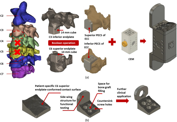
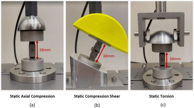
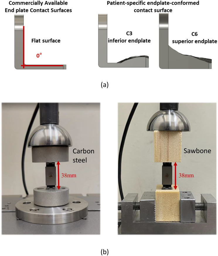
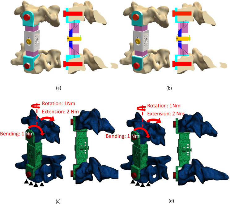
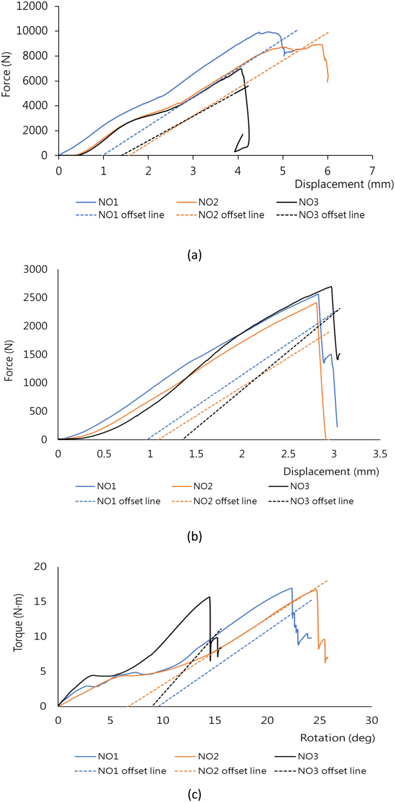
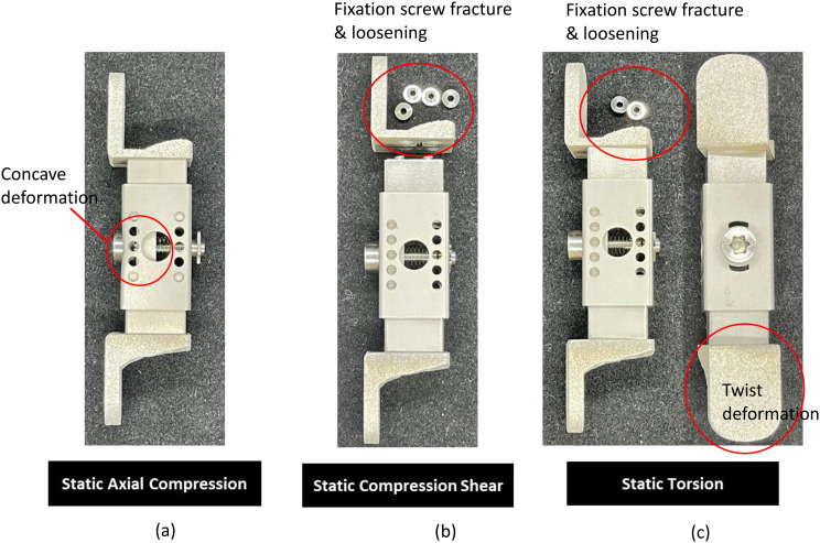
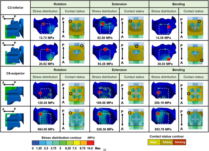
This study developed a new titanium cervical spine expandable corpectomy cage (ECC) that consisted of two superior/inferior patient-specific endplate-conformed contact surfaces (PECSs) fabricated through 3D printing and a standardized centrally expandable mechanism (CEM) manufactured using traditional machining. Fatigue testing was conducted to evaluate whether the components of ECC could be assembled using different manufacturing methods to meet the functional testing requirements in compliance with FDA regulations. The titanium 3D-printed superior/inferior PECSs were designed based on the CT images/CAD system to assembly with a CNC milling/precision wire cutting cuboid CEM (14 mm square cross-section) expansion driven by a set of sliders interlocked via key and keyway mechanisms for the ECC of two-segmental vertebral bodies. The ECC underwent FDA-compliant static/dynamic compression, shear, torsion, subsidence tests and finite element (FE) analysis for understanding the stress differences on endplates between PECS and flat-shaped endplate contact surface (FECS). Stiffness/yield strength were found to be 2127 ± 146 N/mm/8547 ± 1213 N for the compression test, 1158 ± 139 N/mm/ 2561 ± 114 N for the shear test, and 1.22 ± 0.32 Nm/deg/16.5 ± 0.58 Nm for the torque test. Some failure samples showed that fixation screws were fractured/loosened under the shear test. The endure limits were 1600 N, 350 N and 1.0 N*m under compression, shear and torsion cyclic load tests, respectively. The results of the static axial compression and static/dynamic compression-shear testing did not meet the acceptance criteria of ISO 23,089. The PECS with higher stiffness value showed that better subsidence resistance was achieved than FECS and was consistent with that the maximum stress value and distribution for the FECS were more harmful than those for the PECS models. This study demonstrated that mechanical testing is essential when assembling 3D-printed components with CNC-manufactured parts in multi-component medical implants, as mismatches in interface behavior may result in mechanical failure. The results of FE analysis and subsidence tests indicated that PECS can decrease stress concentration between the ECC and endplates to present better performance for subsidence resistance.

Keywords: 3D printing; Cage; Dynamic test; Expansion; Patient-specific.


Conflict of interest statement

Declarations. Ethics approval and consent to participate: N/A. Consent for publication: Not applicable. Competing interests: The authors declare no competing interests.

Figures

Fig. 1
Fig. 1
(a) PECS illustration of the generation process including CT image reconstruction and CAD Boolean operation with a 14 mm cube block. The ECC is shown assembled by CEM and PECSs. (b) Detailed design including countersink and screw holes on the PECS surface and potential side wall design for further clinical application
Fig. 2
Fig. 2
(a) Superior/inferior PECSs manufactured using metal 3D printing; (b) CEM manufactured using CNC milling and precision wire cutting; (c) The ECC assembled by CEM and PECSs (left: expanded and right: not expanded)
Fig. 3
Fig. 3
(a) ECC structure illustration not yet expanded, left: cross-sectional structure and right: ECC dimension and instrument driven; (b) ECC structure illustration expanded, left: cross-sectional structure and right: 13 mm of expansion range for the ECC and instrument driven
Fig. 4
Fig. 4
Biomechanical test setup for (a) Axial compression; (b) Compression shear and (c) Torsion
Fig. 5
Fig. 5
(a) FECS design concept modified from PECS; (b) Illustrations of subsidence test for left: used carbon steel clamping block and right: used Sawbone clamping block
Fig. 6
Fig. 6
FE analysis for (a) ECC solid models, left: with using PECS and right with using FECS; (b) FE mesh models and loading/boundary conditions for left: with using PECS and rught: with using FECS
Fig. 7
Fig. 7
(a) Load-displacement curve under axial compression test; (b) Load-displacement curve under compression shear test; (c) Torque-degree curve under torsion test
Fig. 8
Fig. 8
Sample failure modes under static loads for (a) The central screw deformed due to the outer frame generated concave deformation with no large damage under axial compression test; (b) No obvious damage was found to the expansion structure/endplate contact surface but the fixation screws were fractured or pulled out under shear compression test; (c) Outer frame showed light torsional deformation and some fixation screws loosening at the CEM/PECS contact surface
Fig. 9
Fig. 9
Sample failure mode under dynamic shear loads with damage occurring at the PECS side wing plate, a set of fractured slider structures were found, caused by the loosening of fixing screws
Fig. 10
Fig. 10
Status of stress distribution and contact areas for ECC used with PECS and FECS under all load condition simulations. Red asterisk at the figures of stress distributions indicated the locations of maximum stress values. Black circle area at the figures of contact area showed the possibility of superior/inferior heavy contact areas of the EEC cage under all loads

References

    1. Elder BD, Lo SF, Kosztowski TA, Goodwin CR, Lina IA, Locke JE, Witham TF. A systematic review of the use of expandable cages in the cervical spine. Neurosurg Rev. 2016;39(1):1. - PubMed
    1. Hur JW, Ryu KS, Ahn S, Kim JS, Chung HJ, Song MS. Anterior cervical corpectomy and fusion in terms of postoperative subsidence and sagittal alignment comparative analysis of 2 different types of titanium mesh cage for single-level. Clin Spine Surg. 2020;33(1):E8–13. - PubMed
    1. Qin R, Chen X, Zhou P, Li M, Hao J, Zhang F. Anterior cervical corpectomy and fusion versus posterior laminoplasty for the treatment of oppressive myelopathy owing to cervical ossification of posterior longitudinal ligament: a meta-analysis. Eur Spine J. 2018;27:1375–87. - PubMed
    1. Zhang Y, Liu H, Yang H, Pi B. Anterior cervical corpectomy and fusion versus discectomy and fusion for the treatment of two-level cervical spondylotic myelopathy: analysis of sagittal balance and axial symptoms. Int Orthop. 2018;42:1877–82. - PubMed
    1. Cappelletto B, Giorgiutti F, Balsano M. Evaluation of the effectiveness of expandable cages for reconstruction of the anterior column of the spine. J Orthop Surg (Hong Kong). 2020;28(1):2309499019900472. - PubMed

LinkOut - more resources