. 2025 Oct 31;16(1):9639.
doi: 10.1038/s41467-025-64637-y.

Dual-band high-dissymmetry circularly polarized luminescence from cholesteric liquid crystals overlaid a gold cluster film

Affiliations

Dual-band high-dissymmetry circularly polarized luminescence from cholesteric liquid crystals overlaid a gold cluster film

Xichen Hao et al. Nat Commun. .

Abstract

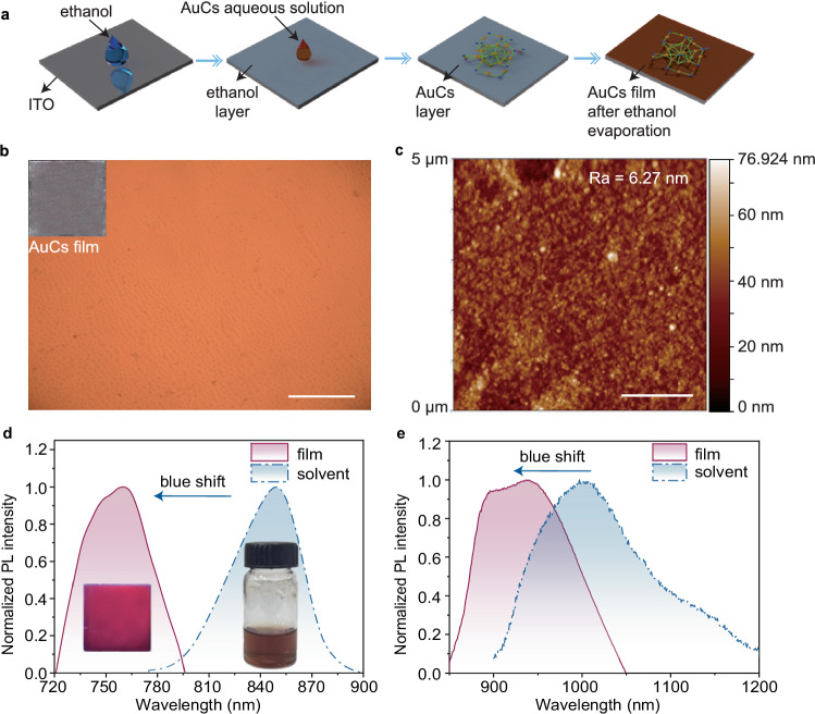
Recently, near-infrared (NIR) circularly polarized luminescence (CPL) has emerged as a research hotspot owing to its unique application prospects. Atomic precision Au clusters (AuCs) have shown excellent biocompatibility and characteristic emission in the NIR region, and have found various applications in biosensing and imaging. Here, we achieve stable and highly dissymmetric CPL in both visible and NIR regions from cholesteric liquid crystals (CLCs) overlaid on a uniform AuCs film. The glum factors (Maximum 2) in the visible and the NIR regions reach 1.8 and 0.7, respectively. AuCs films are prepared by the anti-solvent precipitation method for the first time. By overlaying wide-band CLCs on the AuCs film, dual CPL is simultaneously realized in both visible and NIR regions. Based on the intrinsic properties of CLCs, electrically tunable, thermally reversible and optically tunable CPL from CLCs/AuCs composites are successfully demonstrated. These features of CLCs/AuCs composites offer possibilities for applications in cryptography and anti-counterfeiting.


Conflict of interest statement

Competing interests: The authors declare no competing interests.

Figures

Fig. 1
Fig. 1. Physical characterization of Au24Cd1(MPA)18 clusters.
a Crystal structure. b XPS spectrum and data fitting of Au 4f level. c XPS spectrum of Cd element’s 3d electrons. d UV-Visible absorption spectrum. e TEM image of Au24Cd1(MPA)18. Scale bar = 20 nm. Enlarged view: scale bar = 2 nm. f Size distribution of Au24Cd1(MPA)18 in water solution. g Au L3-edge XANES of Au24Cd1(MPA)18, Au25(MPA)18 Au foil. h Cd K-edge XANES spectra of Au24Cd1MPA18 and Cd foil. i Cd K-edge FT-EXAFS spectra and their fitting results in R-space.
Fig. 2
Fig. 2. Fabrication and characterization of Au clusters (AuCs) films.
a Schematic illustration of the fabrication process of AuCs film using the anti-solvent precipitation method. b Microscope image of AuCs film. The illustration shows a photograph of the AuCs film prepared by the anti-solvent deposition method captured with a camera. Scale bar = 100 μm. c AFM image of AuCs film. Scale bar = 1 μm. d PL spectra of the AuCs solution and film in the visible region. The inset shows photographs of AuCs solution and film under excitation by a 365 nm UV lamp. e PL spectra of the AuCs solution and film in the near-infrared (NIR) region.
Fig. 3
Fig. 3. Structure and characterizations of cholesteric liquid crystals/Au clusters (CLC/AuCs) composites.
a Configuration of the CLC/AuCs composites. The left panel in (b) and (c) shows POM images of CLC/AuCs composites in (b) the visible region (VIS) and (c) the near-infrared (NIR) region. The illustration in (b) shows the picture of sample with UV irradiation (365 nm) was captured with camera in (b). Scale bar = 50 μm. The right panel in (b, c) shows a large-field view of the CLC/AuCs composites in (b) the visible region and (c) the NIR region. Scale bar = 100 μm. d, f CPL spectra of CLC/AuCs composites and the AuCs film. The solid (dashed) curve corresponds to right (left)-handed composites in (d) the visible region and (f) the NIR region. Variation in the glum factors against wavelength of CLC/AuCs composites in the (e) visible region and (g) the NIR region. h Dual-emission CPL spectra of CLC/AuCs composites in the visible and the NIR regions. i The glum factors of dual-emission CLC/AuCs composites change against wavelength in the visible and the NIR regions.
Fig. 4
Fig. 4. Graphic patterning of cholesteric liquid crystals/Au clusters (CLC/AuCs) composites and electrically switchable polarization of CPL.
a Schematic illustration of the fabrication process of the AuCs film with designed graphic patterns. b Photograph of the CLC/AuCs composites under the UV radiation (365 nm) in the visible (VIS) region. Scale bar = 5 mm. c Photograph of the CLC/AuCs composites under the radiation of 808 nm laser in the near-infrared (NIR) region. Scale bar = 5 mm. Photograph of the CLC/AuCs composites under the UV radiation (365 nm) in the visible region when the quarter-wave plate and linear polarizer are oriented at (d) 45° and (e) 135°, respectively. Scale bar = 5 mm. Photograph of the CLC/AuCs composites under the radiation of 808 nm laser in the NIR when the quarter-wave plate and linear polarizer are oriented at (f) 45° and (g) 135°, respectively. Scale bar = 5 mm. h The schematic diagram of the CLC/AuCs composites under applied voltage. Variation in the glum factors against wavelength of the CLC/AuCs composites under different voltages in (i) the visible region and (j) the NIR region. Reflectance spectra of CLC/AuCs composites under different voltages in (k) the visible region and (l) the NIR region. m The glum factors of the CLC/AuCs composites under the different voltages in the visible and the NIR regions.
Fig. 5
Fig. 5. Thermally switchable CPL for anti-counterfeiting application.
Variation in the reflection band of CLC in the CLC/AuCs composites as a function of temperature in (a) the visible (VIS) region and (b) the near-infrared (NIR) region. c Variation in the glum factors of CLC/AuCs composites as a function of temperature in the visible and the NIR regions. d Reversible changes of the glum factors of CLC/AuCs composites against the repeated temperature cycles from 25 °C to 59 °C in the visible region. e Photographs of the CLC/AuCs composite loaded with the “TJU” as a function of temperature under UV light irradiation (365 nm). Scale bar = 5 mm.
Fig. 6
Fig. 6. Optically tunable CPL.
a Schematic diagram of the light-induced increase in CLC pitch. b Variation in the reflection band of CLC in the CLC/AuCs composites as a function of the exposure time. Photographs of the CLC/AuCs composites loaded with the “TJU” as a function of the exposure time under UV light irradiation (365 nm) at (c) 0 S, (d) 6S, (e) 9 S. Scale bar = 5 mm.

References

    1. Diao, Z., Kraus, M., Brunner, R., Dirks, J.-H. & Spatz, J. P. Nanostructured stealth surfaces for visible and near-infrared light. Nano Lett.16, 6610–6616 (2016). - PubMed
    1. Hou, C.-C. et al. Near-infrared and mid-infrared semiconductor broadband light emitters. Light Sci. Appl.7, 17170–17170 (2017). - PMC - PubMed
    1. Nelidova, D. et al. Restoring light sensitivity using tunable near-infrared sensors. Science368, 1108–1113 (2020). - PubMed
    1. Pfeifer, L., Hoang, N. V., Scherübl, M., Pshenichnikov, M. S. & Feringa, B. L. Powering rotary molecular motors with low-intensity near-infrared light. Sci. Adv.6, eabb6165 (2020). - PMC - PubMed
    1. Liu, G. et al. Laser-driven broadband near-infrared light source with watt-level output. Nat. Photon.18, 562–568 (2024).

LinkOut - more resources