Review
. 2025 Oct 25;10(43):50773-50794.
doi: 10.1021/acsomega.5c08801. eCollection 2025 Nov 4.

Phosphate-Based Approaches for Dechlorination and Treatment of Salt Waste from Electrochemical Processing of Used Nuclear Fuel: A Perspective on Recent Work

Affiliations
Review

Phosphate-Based Approaches for Dechlorination and Treatment of Salt Waste from Electrochemical Processing of Used Nuclear Fuel: A Perspective on Recent Work

Jonathan S Evarts et al. ACS Omega. .

Abstract

Phosphate-based reagents are being considered by the U.S. Department of Energy (DOE) Office of Nuclear Energy to process halide salt-based nuclear wastes for stabilization prior to disposal. As evidenced by the Experimental Breeder Reactor-II (EBR-II) project, electrochemical processing (pyroprocessing) can be employed to recover uranium and other actinides for reintegration into the nuclear fuel cycle from metallic fuels. The resultant salt-based wastes generated from electrochemical processing of EBR-II fuel contains fission products within a LiCl-KCl eutectic salt that necessitate appropriate disposal. This paper provides an overview of recent efforts to support halide-based salt waste treatment for disposition, as well as a basis for comparison with other related efforts in salt waste treatment through salt partitioning initiatives. The U.S. DOE has selected a phosphate waste form reference material for further investigation and longer-term studies.


Figures

1
1
A representative schematic of ER operation, including (a) used nuclear fuel (UNF) prior to electrorefining and (b) following electrorefining. In (b), the remaining products following treatment are shown, including uranium metal adhered to the cathode, Group I and II elements, lanthanides, and transuranics (TRU) dissolved in the salt bath as chlorides.
2
2
Summary of ER salt processing and waste form options for different waste streams, including ultrastable H–Y zeolite (USHYZ), silica aluminophosphate (SAP), glass-bonded sodalite (GBS), lead tellurite (Pb–Te–O) glass, zinc-in-titania (ZIT), lanthanide (alumino)­borosilicate (LABS) glass, and iron phosphate (Fe–P–O) glass. Note that RE denotes rare earth (elements). Reprinted in part with permission from Riley et al. Copyright 2020 American Chemical Society.
3
3
Process flow diagram showing (a) pyroprocessing as well as (b) the process of dehalogenating salt wastes and the process of vitrifying the dehalogenated product into a waste form for disposal. Reprinted in part with permission from Murray et al. Copyright 2024 American Chemical Society. Licensed under CC-BY-NC-ND 4.0.
4
4
(a) Pictures of the solid condensates collected after salt dehalogenation showing (left) an attempted dehalogenation with Fe2O3 in the crucible with ADP and (right) a simple dehalogenation with only ADP. (b) Pseudocolored scanning electron micrograph of the recovered condensate product from the attempted one-step process. Reprinted with permission from Riley et al. Copyright 2021 Pacific Northwest National Laboratory.
5
5
Schematic of the generation-2 dechlorination apparatus showing the (a) dual Allihn condenser system, (b) jumper piece between the condensers and the furnace glassware, (c) furnace with off-gas glassware (circled numbers are different pieces of glassware discussed in the text), (d) more detailed view of the furnace showing all five separately heated zones, (e) support for the furnace, and (f) 250 mL alumina crucible for holding the reactants. The drawings are not to scale. Reprinted in part with permission from Riley et al. Licensed under CC-BY-NC-ND 4.0.
6
6
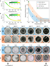
Results from dechlorination with a phosphoric acid precursor and the SSM simulant. Mass loss during dechlorination of a simple salt mixture in an (a) air and (b) argon environments. (c) Residual chlorine content in samples produced from phosphoric acid–based dechlorination of SSM simulant (P/Cl = 1). The legend labels samples by their salt mixture, phosphate precursor, and dechlorination environment. Sample appearance after dechlorination of the SSM simulant in (d) air and (e) argon environments. Sample appearance after dechlorination of the ERV3 mixture in (f) air and (g) argon environments. Callouts show the residual chlorine content for both the air and argon ERV3 samples. Reprinted in part with permission from Werth et al. Copyright 2025 American Chemical Society.
7
7
Expanded P2O5–Fe2O3–salt ternary diagram for DPF3 (red) and DPF5 (blue) series glasses in (a) mol % and (b) mass %. The location of the DPF5–336 reference material is shown as “0.336” and designated with the green arrow. This figure was modified from the original by Ebert and Fortner , and is reprinted with permission. Copyright 2019 Argonne National Laboratory.
8
8
Cooling curves evaluated for processing DPF5–336. Curve SCC#1 is a theoretical curve. SCC#2, #3, and #5 results are found in Riley et al. and SCC#4 results are found in Riley and Chong. The numbers drawn on the horizontal line represent the time (minutes) required to get to 400 °C. Reprinted with permission from Riley et al. Copyright 2023 Pacific Northwest National Laboratory.
9
9
Summary of measured-versus-targeted glass compositions following dechlorination during crucible evaluation tests with (a) alumina, (b) silica (fused quartz), (c) glassy carbon, (d) nickel, (e) AX05 boron nitride, (f) HP boron nitride, and (g) ZSBN boron nitride. Each plot has an inset that is a magnified view of the 0–6 mass % window; the common legend is shown on the bottom right. Each data point is an average of three measurements and error bars are included as the standard deviation of those measurements. Each plot also has an inset showing a picture of the crucible used for these experiments; the scalebar shown for each represents 1 cm. Reprinted with permission from Riley et al. Copyright 2020 Elsevier.
10
10
Corrosion rate, measured at the melt line, for three commercially produced refractories (cylindrical rods) rotated at 9.2 rpm for 24 h in an iron phosphate melt at the temperature shown. Reprinted with permission from Day and Ray. Copyright 2013 Idaho National Laboratory.
11
11
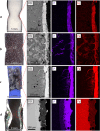
Results of corrosion by DPF5–336 of (a) alumina, (b) Monofrax K-3, and (c) fused quartz for 4 h and (d) stainless steel 316L for 1 h in an argon atmosphere are shown. The blue hue in the optical image in (c) is the epoxy behind the quartz bar. Column-1 represents optical micrographs, column-2 represents scanning electron micrographs, and the two right columns represent energy dispersive X-ray spectroscopy elemental dot maps for P and Fe. Reprinted in part with permission from Werth et al. Copyright 2025 Pacific Northwest National Laboratory.
12
12
Figure showing the typical leaching progression of glass waste forms. Reprinted with permission from Marcial et al. Copyright 2024 Pacific Northwest National Laboratory.
13
13
Cumulative normalized elemental release [NL­(i)] for NBS3–5 compared to DPFR-I (DPF cooling rate most closely representing the NBS3–5 cooling rate) and DPFR-Q (quenched DPF5–336) waste forms showing values for (a) NL­(K), (b) NL­(Cs), (c) NL­(Li), and (d) NL­(Na). (e) Alkali metal dissolution rates [DR­(i)] for samples in this study (NBS3–0, NBS3–2.5, NBS3–5, NBS3–10, NBS3–15), compared to waste glass standards, i.e., Advanced Fuel Cycle Initiative (AFCI), SON68, and Laboratory Reference Material (LRM). Reprinted with permission from Evarts et al. Copyright 2025 American Chemical Society.

References

    1. U.S. Congress , Accelerating Deployment of Versatile, Advanced Nuclear For Clean Energy Act. U.S. Government Printing Office: Washington, DC, 2023, Public Law 118-182.
    1. McCloy J. S., Riley B. J., Dixon Wilkins M. C., Evarts J. S., Bussey J., Vienna J. D., Bingham P. A., Gregg D. J., Ojovan M., Schuller S., Uruga K., Perret D., Regnier E., Giboire I., Um W., Xu K., Goel A., Kruger A. A.. International perspectives on glass waste form development for low-level and intermediate-level radioactive waste. Mater. Today. 2024;80:594–618. doi: 10.1016/j.mattod.2024.08.025. - DOI
    1. Ingersoll D. T., Houghton Z. J., Bromm R., Desportes C.. NuScale small modular reactor for Co-generation of electricity and water. Desalin. 2014;340:84–93. doi: 10.1016/j.desal.2014.02.023. - DOI
    1. Schlegel, J. P. ; Bhowmik, P. K. . Chapter 14Small modular reactors. In Nuclear Power Reactor Designs; Wang, J. , Talabi, S. , Leon, S. B. y. , Eds.; Academic Press, 2024; pp 283–308.
    1. International Atomic Energy Agency . Small Modular Reactors: Advances in SMR Developments 2024: Vienna International Centre: Vienna, Austria, 2024.

LinkOut - more resources