. 2025 Nov 14;16(1):10011.
doi: 10.1038/s41467-025-64971-1.

Van-der-Waals-forces-modulated graphene-P-phenyl-graphene carbon allotropes

Affiliations

Van-der-Waals-forces-modulated graphene-P-phenyl-graphene carbon allotropes

Huanxin Li et al. Nat Commun. .

Abstract

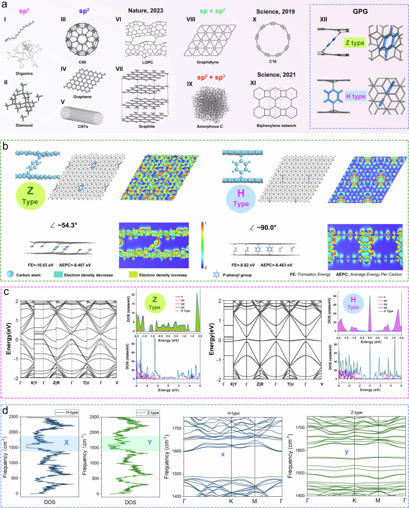
Graphene has received much attention due to its monoatomic, unique two-dimensional structure, which results in remarkable mechanical, physical, and electrical properties. However, synthesizing high-quality graphene-based composites with high conductivity and ionic mobility remains challenging. Here, we report an allotrope to the nanocarbon family, Graphene-P-phenyl-Graphene, synthesized by inserting π-π-conjugated p-phenyls between graphene layers and connecting them via C-C σ bonds. Graphene-P-phenyl-Graphene is thermally and dynamically stable, as verified by density functional theory and molecular dynamics, and can be produced at kilogram scale. The p-phenyl bridges swell the layer spacing from ~0.34 to ~0.56 nm, reducing van der Waals forces and enhancing electron delocalization. Electrons in these separated graphene layers benefit from low mass and efficient 3D screening of charge scattering, resulting in high Hall mobility (10,000-13,000 cm² V⁻¹ s⁻¹) in freestanding films. The expanded spacing also enables decoupling of layer electrons and rapid ion storage and transport-even for large ions. For example, potassium-ion batteries using Graphene-P-phenyl-Graphene exhibit high reversible capacity, long-term stability, and high charge-discharge rates. Graphene-P-phenyl-Graphene holds promise for large-scale, portable, high-performance electronics with energy storage capabilities.


Conflict of interest statement

Competing interests: The authors declare no competing interests.

Figures

Fig. 1
Fig. 1. The atomic structures of various carbon allotropes and band structures and corresponding electron and phonon DOS for Z-type and H-type GPG.
a Different types of carbon allotropes with sp, sp2 and sp3-hybridized (a-I: organic carbon skeleton; a-II: diamond; a-III: C60; a-IV: Graphene; a-V: CNTs; a-VI: LOPC; a-VII: Graphite; a-VIII: Graphdiyne; a-IX: Amorphous Carbon; a-X: C18; a-XI: Biphenylene network; a-XII: Z-type GPG (top) and H-type GPG (bottom)); b The structures and Charge Density Difference (CHGDIFF) of Z- and H-type GPG allotropes (Blue ball: carbon atom; Grey stick structure: C-C bond; blue stick structure: highlighted p-phenyl group; Green area in CHGDIFF image: electron density decrease; yellow area in CHGDIFF image: electron density increase; the electron density increases relatively from deep blue (minimal, 0) to red (maximum, 1) on the colour bar); c The band structures and corresponding electron DOS of Z-type (left) and H-type (right) GPG allotropes; d The phonon density of states and dispersion profiles of Z- and H-type GPG allotropes (First: phonon DOS of H-type GPG; Second: phonon DOS of Z-type GPG; Third: the phonon dispersion of H-type GPG in region X; Fourth: the phonon dispersion of Z-type GPG in region Y).
Fig. 2
Fig. 2. Synthesis and characterizations of H-type GPG.
a The schematic for layer-by-layer synthesis of GPG from high quality CVD graphene; b The 3D and (c) detailed side view CHGDIFF of GPG between the layers; d ACTEM image of GPG top view; e AFM image of GPG top view; f The hight profile for single/double-layer GPG edge (grey ball are carbon atoms); g TEM image of GPG; h Enlarged TEM and ACTEM (inserted) images of GPG; i ACTEM image and modelling structure of the top view for H-type GPG: the original ACTEM image (top left); the theoretical model of of H-type GPG (top right); the alignment of ACTEM image and theoretical model of H-type GPG (bottom); j Side view of the modelling structure of H-type GPG (The grey sticks represent C–C bonds. All balls denote carbon atoms, with the pink and purple ones corresponding to the same set of carbon atoms in the top view (i) and side view (j), respectively. The ball-shaped atoms are those visible in the top view and are highlighted accordingly).
Fig. 3
Fig. 3. Synthesis and characterizations of Z-type GPG.
a The massive production of GO-P-GO from graphene oxide ink; b The GPG formed by pyrolysis of GO-P-GO; c The optical image of GPG film; d side view of X-CT image for the GPG film and 3D pore-network of the GPG film; e TEM image of multi-layer graphene; f TEM image, g enlarged TEM image, and h HRTEM image of Z-type GPG; i enlarged HRTEM (first), QSTEM simulation (second), theoretical model (third, grey balls and sticks are the carbon atoms and C-C bonds in graphene plane; blue balls and sticks are the carbon atoms and C-C bonds in the p-phenyl group), and CHGDIFF images (fourth) of Z-type GPG; j Typical TEM image, k Raman spectrum and l corresponding G/G+ peaks for Z-type GPG.
Fig. 4
Fig. 4. Theoretical and experimental performances of GPG for potassium ion batteries.
a The van der Waals forces within 2LG (I) and GPG (II) and their energy barriers for potassium ion migration (a-I: interaction between graphite layers; a-II: interaction between GPG layers; a-III: visualized interaction between graphite layers with a potassium ion insertion; a-IV: visualized interaction between GPG layers with a potassium ion insertion; a-V: energy barrier for potassium ion migration in graphite layers; a-VI: energy barrier for potassium ion migration in GPG layers; Blue: Attractive force; Green: Neutral; Red: Repulsive force; Blue ball: Carbon atom; White ball: Hydrogen atom); b the charge-discharge profiles for potassium ion battery working at 1 C and 20 C; c the rate performance for PIBs and d the relative CE; e the charge-discharge profiles at ultra-high rate of 210 C (1 C = 300 mA g–1) for PIBs with RGO and GPG negative electrodes (insert) the enlarged charge-discharge curves at 1000 and 2000 min; f the long-term cycle stability and CE of GPG based PIB at 2 C for 20000 cycles (the testing temperature is 25 ± 1 °C and cutoff voltages is 0.01-3.0 V with a safe voltage range from −2.0 to 5.0 V for overpotential protection); g the comparison of our work with other battery systems.

References

    1. Kroto, H. W., Heath, J. R., O’Brien, S. C., Curl, R. F. & Smalley, R. E. C60: Buckminsterfullerene. Nature318, 162–163 (1985).
    1. Iijima, S. & Ichihashi, T. Single-shell carbon nanotubes of 1-nm diameter. Nature363, 603–605 (1993).
    1. Novoselov, K. S. et al. Electric field effect in atomically thin carbon films. Science306, 666–669 (2004). - PubMed
    1. Kaiser, K. et al. An sp-hybridized molecular carbon allotrope, cyclo[18]carbon. Science365, 1299–1301 (2019). - PubMed
    1. Pan, F. et al. Long-range ordered porous carbons produced from C60. Nature614, 95–101 (2023). - PubMed

LinkOut - more resources