Patterns of lambda Int recognition in the regions of strand exchange
- PMID: 6235918
- PMCID: PMC2211524
- DOI: 10.1016/0092-8674(83)90355-0
Patterns of lambda Int recognition in the regions of strand exchange
Abstract
Int protein has two classes of binding sites within the phage att site: the arm-type recognition sequences are found in three specific sites that are distant from the region of strand exchange; the junction-type recognition sequences occur as inverted pairs around the crossover region in both attP and attB. During recombination between attP and attB each of the four DNA strands is cut at a homologous position within each of the junction-type Int binding sites. In all four junction-type sites Int protein interacts primarily with the same face of the DNA helix, as determined by those purine nitrogens that are protected against methylation by dimethylsulfate. Efficient secondary attachment sites for lambda contain sequences with partial homology to the junction-type binding sites. In addition, the sequence between, but not part of, the two junction-type sites (the overlap region) is strongly conserved in secondary att sites. Thus, in the vicinity of strand exchange, attP and a recombining partner, such as attB, are very similar; each comprises two junction-type Int recognition sites and an overlap (crossover) region.
Figures
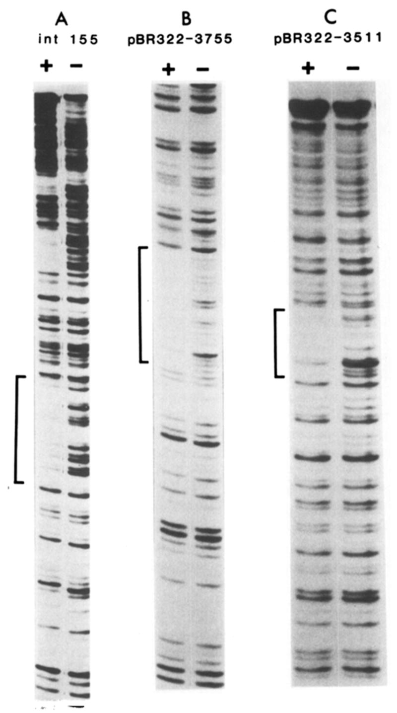
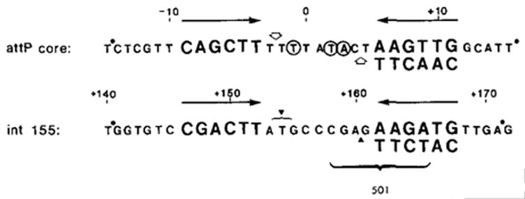
 ) Sites cut by Int during recombination (Mizuuchi et al., 1981; N. Craig and H. Nash, personal communication). The endpoints of xin-promoted deletions (▼) (Gritzmacher and Weisberg, personal communication) and the 8 bp region containing the att2501 deletion endpoint (Ross et al., 1982) are indicated within the int155 site.

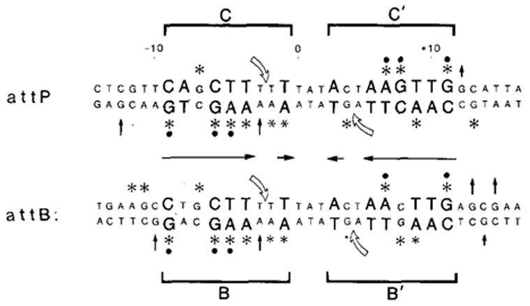
 ) Positions cut by Int during recombination (Mizuuchi et al., 1981; Craig and Nash, personal communication). The four junction sites are referred to as C and C′ (for core) in attP and B and B′ in attB. Protected positions that are conserved in three or four of the sites (●).
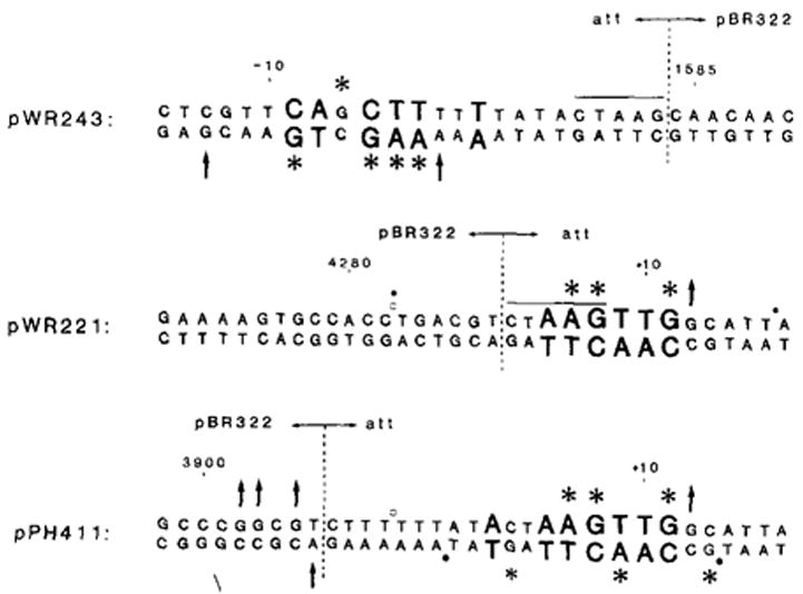
 ). In pWR243 and pWR221, these new junctions occur at the right or left ends of the Dde site (CTAAG). In pPH411, the new junction was created at the Hinc II site in pBR322 (3906) and the Alu site in att (−6); no new restriction site was generated, and one C was deleted during fusion formation. Numbering refers to att sequence (Figure 5) or to pBR322 sequence (Sutcliffe, 1979).
 ) and lower (
 ) strands of attP and attB are indicated. The overlap region comprises the 7 bp between the cut positions. Secondary site sequences are aligned according to cut positions, as judged by sequence analysis of the secondary prophage sites (see Table 1 for references; sites are in the same order of measured or predicted efficiency as in Table 1). Many secondary sites contain several bases of continuous homology with the attP core, which may include one or both of the cut positions; in these cases, the cuts in the secondary sites are assumed to occur in the same relative positions as in the attP and attB cores. In some cases better sequence matches with the recognition site are found ±1 bp from the standard spacing (see Table 1), but are not indicated here. Sequence homologies in the overlap region are not given special representation, with the exception of the two positions (−1 and +3) that are conserved positions in the Int consensus sequence.
References
-
- Anderson WF, Ohlendorf DH, Takeda Y, Matthews BW. Structure of cro repressor from bacteriophage lambda and its interaction with DNA. Nature. 1981;290:754–758. - PubMed
-
- Bidwell K, Landy A. Structural features of X site-specific recombination at a secondary att site in ga/T. Cell. 1979;16:397–406. - PubMed
-
- Christie GE, Platt T. A secondary attachment site for bacteriophage λ in trpC of E. coli. Cell. 1979;16:407–413. - PubMed
Publication types
MeSH terms
Substances
Grants and funding
LinkOut - more resources
Full Text Sources
Other Literature Sources