Review
. 1997 Jan 1;17(1):438-58.
doi: 10.1523/JNEUROSCI.17-01-00438.1997.

Anatomic organization of the basilar pontine projections from prefrontal cortices in rhesus monkey

Affiliations
Review

Anatomic organization of the basilar pontine projections from prefrontal cortices in rhesus monkey

J D Schmahmann et al. J Neurosci. .

Abstract

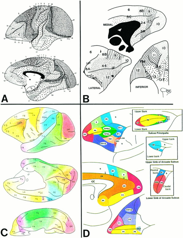
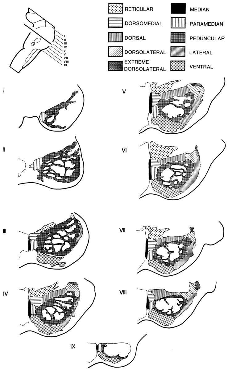
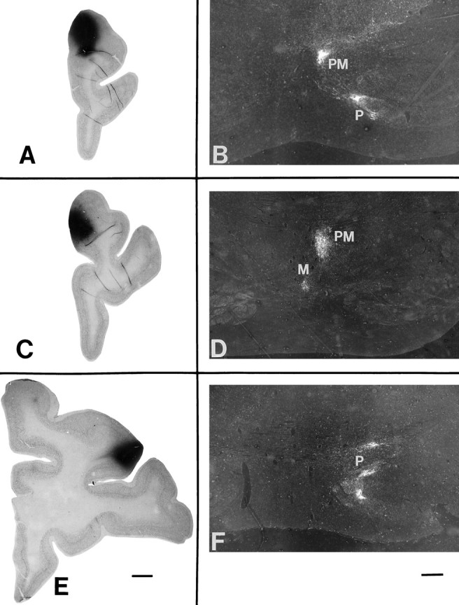
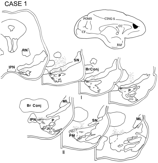
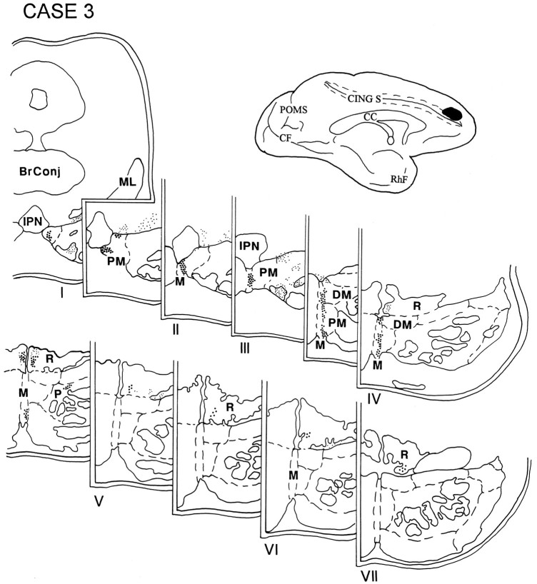
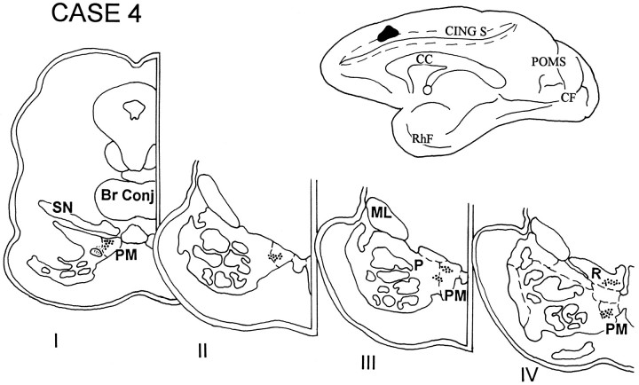
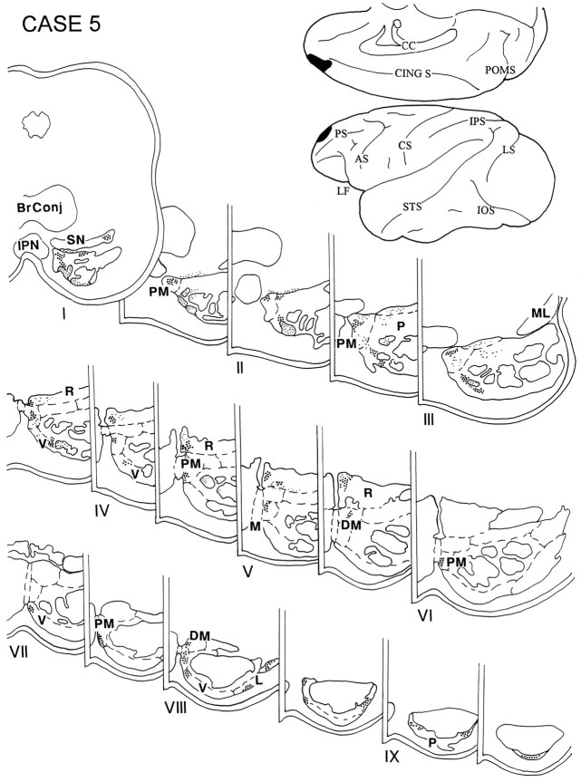
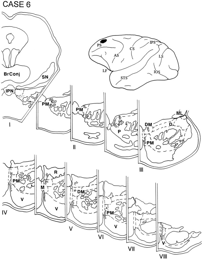
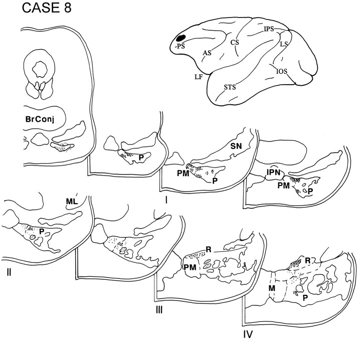
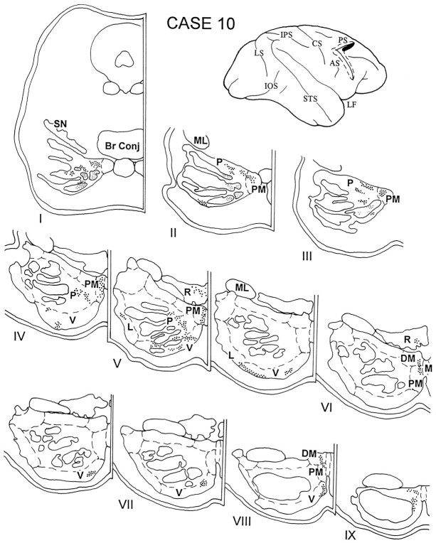
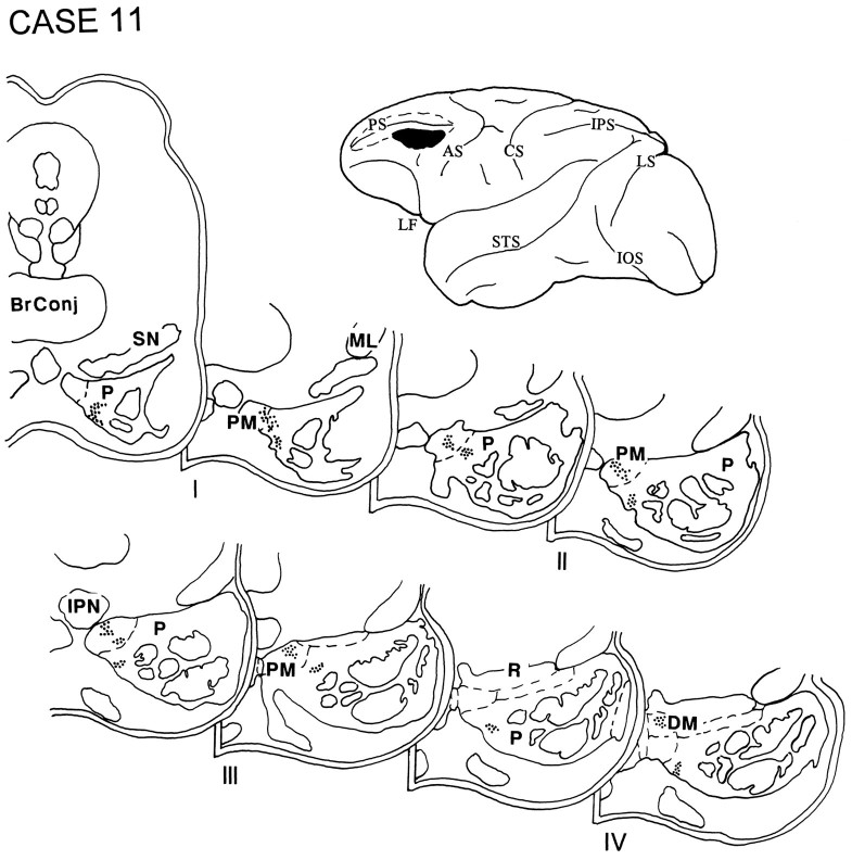
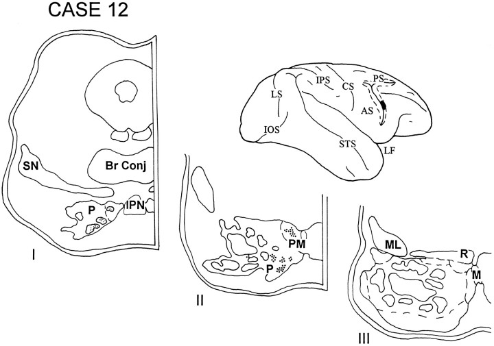
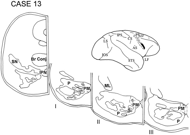
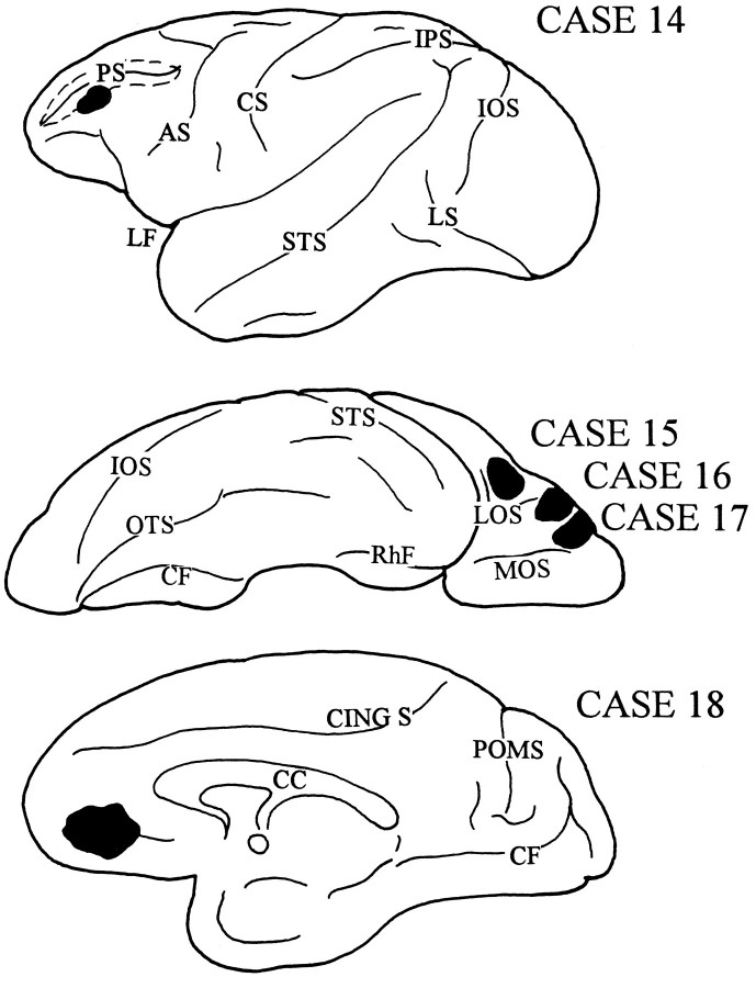
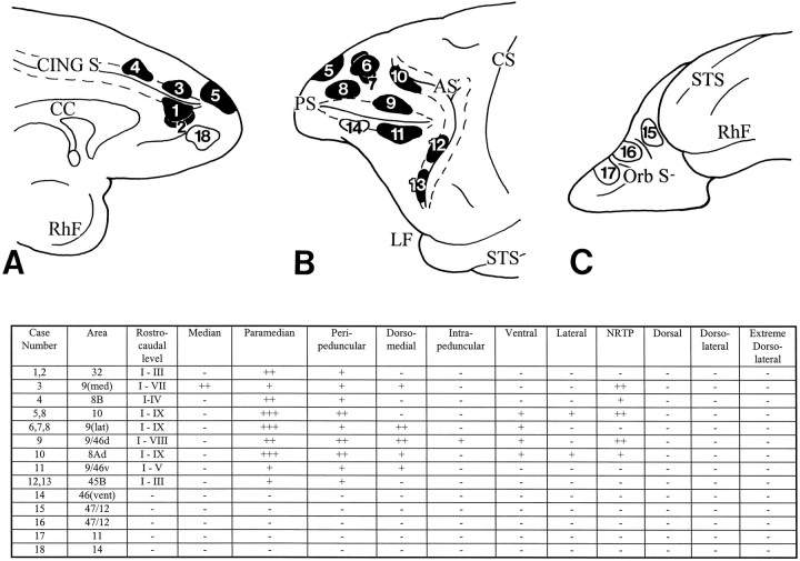
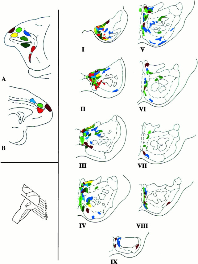
In our ongoing attempt to determine the anatomic substrates that could support a cerebellar contribution to cognitive processing, we investigated the prefrontal cortical projections to the basilar pons. A detailed understanding of these pathways is needed, because the prefrontal cortex is critical for a number of complex cognitive operations, and the corticopontine projection is the obligatory first step in the corticopontocerebellar circuit. Prefrontopontine connections were studied using the autoradiographic technique in rhesus monkey. The pontine projections were most prominent and occupied the greatest rostrocaudal extent of the pons when derived from the dorsolateral prefrontal convexity, including areas 8Ad, 9/46d, and 10. Lesser pontine projections were observed from the medial prefrontal convexity and area 45B in the inferior limb of the arcuate sulcus. In contrast, ventral prefrontal and orbitofrontal cortices did not demonstrate pontine projections. The prefrontopontine terminations were located preferentially in the paramedian nucleus and in the medial parts of the peripeduncular nucleus, but each cortical area appeared to have a unique complement of pontine nuclei with which it is connected. The existence of these corticopontine pathways from prefrontal areas concerned with multiple domains of higher-order processing is consistent with the hypothesis that the cerebellum is an essential node in the distributed corticosubcortical neural circuits subserving cognitive operations.


Figures

Fig. 1.
Fig. 1.
Diagrams of the cerebral hemispheres of rhesus monkey illustrating the architectonic areas of the prefrontal cortices according to the designations of Brodmann (1909) (A),Walker (1940) (B), von Bonin and Bailey (1947)(C), and Petrides and Pandya (1994) (D). This figure illustrates the extent of the PFC, and the earlier nomenclature is presented to assist in the interpretation of the results of the studies that are cited in Table 1.
Fig. 2.
Fig. 2.
Diagram showing the subdivisions of the pontine nuclei in the transverse plane (perpendicular to the long axis of the pons) according to Nyby and Jansen (1951), with modifications according to our observations (Schmahmann and Pandya, 1989, 1991).I–IX represent the rostrocaudal levels at equal intervals through the pons.
Fig. 3.
Fig. 3.
Light-field photographs of coronal sections through isotope injections in three representative cases(left), and dark-field photomicrographs of the resulting anterogradely transported terminal label in the nuclei of the ipsilateral basis pontis (right). A, Area 10 injection in case 5, with terminal label seen in B in level III of the pons in the paramedian (PM) and peripeduncular (P) nuclei. C, Isotope injection in case 2 in area 9 at the medial convexity, with terminal label seen in D in level II of the pons in the median (M) and paramedian nuclei. E, Injection site in case 9, in area 9/46d, with terminal label in level II of the pons (F) in the paramedian nucleus. Injection sites (A, C, E): scale bar (shown in E), 20 mm; pontine terminations (B, D, F): scale bar (shown in F), 2 mm.
Fig. 4.
Fig. 4.
Diagram illustrating the medial surface of the cerebral hemisphere of case 1, in which the isotope injection (shown inblack) was placed in the medial PFC and involved area 32. The resulting fibers (small black dots) were present in the rostral third of the ipsilateral pons. The terminal label (large black dots) was distributed primarily in the medial portion of the peduncular and peripeduncular nuclei and in the paramedian nucleus. Abbreviations for cerebral hemispheres (Figs.4, 5, 6, 7, 8, 9, 10, 11, 12, 13, 14, 15, 16, 17): AS, arcuate sulcus; CING S, cingulate sulcus; CC, corpus callosum;CF, calcarine fissure; CS, central sulcus; IOS, inferior occipital sulcus;IPS, intraparietal sulcus; LF, lateral (Sylvian) fissure; LS, lunate sulcus; Orb S, orbital sulcus; OTS, occipitotemporal sulcus;POMS, parieto-occipital medial sulcus;PS, principalis sulcus; Rh F, rhinal fissure; STS, superior temporal sulcus. Abbreviations for brainstem sections (Figs. 4, 5, 6, 7, 8, 9, 10, 11, 12, 13, 14, 15, 16, 17): Br Conj, brachium conjunctivum; D, dorsal pontine nucleus;DL, dorsolateral pontine nucleus; DM, dorsomedial pontine nucleus; EDL, extreme dorsolateral pontine nucleus; IPN, interpeduncular nucleus;L, lateral pontine nucleus; M, median pontine nucleus; ML, medial lemniscus;NRTP, nucleus reticularis tegmenti pontis;P, peduncular nucleus (peripeduncular vs intrapeduncular not differentiated in the diagrams); PM, paramedian pontine nucleus; R, nucleus reticularis tegmenti pontis;RN, red nucleus; SN, substantia nigra;V, ventral pontine nucleus.
Fig. 5.
Fig. 5.
Diagram illustrating the medial surface of the cerebral hemisphere of case 3, in which the isotope was placed above the cingulate sulcus in the rostral part of the superior frontal gyrus and involved the rostral and medial part of area 9. Terminal label was distributed in the rostral two-thirds of the ipsilateral pons and was present in the median nucleus, the paramedian and dorsomedial nuclei, and the NRTP. The contralateral NRTP also had a small projection in between pontine levels IV and V.
Fig. 6.
Fig. 6.
Diagram illustrating the medial surface of the cerebral hemisphere of case 4, in which isotope was injected in the medial surface of the hemisphere above the cingulate sulcus at a level corresponding to the rostral tip of the corpus callosum and involved area 8B. The terminal label was distributed in the rostral half of the ipsilateral pons and in the paramedian nucleus, the medial part of the peripeduncular nucleus, and the NRTP.
Fig. 7.
Fig. 7.
Diagram illustrating the medial and lateral surfaces of the cerebral hemisphere of case 5, in which the isotope was placed in the rostral part of the PFC and involved the medial and dorsal sectors of area 10. Terminal label was observed in levels I–IX of the ipsilateral pons and involved the paramedian, peripeduncular, and dorsomedial nuclei and the NRTP. A small amount of label was noted in the ventral and lateral nuclei at caudal levels of the pons.
Fig. 8.
Fig. 8.
Diagram illustrating the lateral surface of the cerebral hemisphere of case 6, in which the isotope was injected into the PFC above the midportion of the principal sulcus and involved lateral area 9. The resulting label throughout the rostrocaudal extent of the ipsilateral pons occupied a thin dorsal–ventral lamella adjacent to the midline, spanning the paramedian nucleus and the medial part of the peripeduncular nucleus as well as the dorsomedial and ventral nuclei and the NRTP.
Fig. 9.
Fig. 9.
Diagram illustrating the lateral surface of the cerebral hemisphere of case 8, in which isotope was placed in the rostral part of the dorsolateral PFC and involved the rostral part of area 9 and dorsal area 10. Label was restricted to the rostral half of the ipsilateral pons and was located primarily in the paramedian and peripeduncular nuclei, with some grain also in the NRTP.
Fig. 10.
Fig. 10.
Diagram illustrating the lateral surface of the cerebral hemisphere of case 9, in which isotope was placed in the caudal part of the upper bank of the principal sulcus and the adjacent gyral cortex and involved area 9/46d (Fig. 9). The label was distributed throughout the rostrocaudal extent of the ipsilateral pons and was present in the peripeduncular, paramedian, and dorsomedial nuclei as well as in the NRTP and the medial part of the ventral nucleus.
Fig. 11.
Fig. 11.
Diagram illustrating the lateral surface of the cerebral hemisphere of case 10, in which the isotope injection was placed in the cortex lying in the rostral bank of the upper limb of the arcuate sulcus and adjacent gyral cortex and involved area 8Ad. Terminal label was present throughout the rostrocaudal extent of the ipsilateral pons, involving primarily the paramedian and dorsomedial nuclei and the medial and ventral parts of the peripeduncular nucleus. In the caudal pons, grains were noted in the ventral and lateral nuclei, with some in the NRTP.
Fig. 12.
Fig. 12.
Diagram illustrating the lateral surface of the cerebral hemisphere of case 11, in which isotope was injected into the caudal part of the ventral bank of the principal sulcus and the adjacent gyral cortex, and involved area 9/46v. Terminal label was present in the rostral half of the ipsilateral pons in the paramedian nucleus, with some label in the dorsomedial nucleus and the medial part of the peripeduncular nucleus.
Fig. 13.
Fig. 13.
Diagram illustrating the lateral surface of the cerebral hemisphere of case 12, in which the isotope injection was placed in the cortex lying in the rostral bank of the lower limb of the arcuate sulcus and involved area 45B. Label was restricted to the rostral third of the ipsilateral pons and was localized in the paramedian nucleus and in the medial and ventral parts of the peripeduncular nucleus.
Fig. 14.
Fig. 14.
Diagram illustrating the lateral surface of the cerebral hemisphere of case 13, in which the injection in area 45B was slightly ventral to that in the previous case. The pattern of terminations in this case was similar to case 12 and involved the paramedian nucleus and the medial and ventral parts of the peripeduncular nucleus.
Fig. 15.
Fig. 15.
Diagrams illustrating the lateral, ventral, and medial surfaces of the cerebral hemispheres of a rhesus monkey, demonstrating the sites of injection that did not result in the transport of terminal label into the basilar pons. In case 14, the isotope was placed in the rostral aspect of ventral area 46; case 15, in the caudal part of the orbital cortex in area 47/12; case 16, in the midlateral part of the orbital cortex in area 47/12; case 17, in the rostral part of the orbital cortex in area 11; and case 18, in the ventral region of the medial PFC in area 14.
Fig. 16.
Fig. 16.
Diagrams and table illustrating the medial (A), lateral (B), and orbital (C) surfaces of the frontal lobe of a rhesus monkey to show the sites of injection of the isotope-labeled amino acid tracer in 18 animals and the resulting distribution pattern of terminations within the nuclei of the ipsilateral basilar pons. Thenumbers in the injection sites correspond to the individual cases. Injections that resulted in terminations in the basilar pons are shaded in black. Those that did not result in label in the pons are unshaded. Terminations were present in different rostro-caudal levels of the pons (I–IX), as well as in characteristic sets of pontine nuclei. The strength of projection in each pontine nucleus is graded absent (−), mild (+), moderate (++), or strong (+++). The injections in cases 1 and 2 were placed in area 32; case 3, in area 9 medially; case 4, in area 8B medially; case 5, in area 10 at both the medial and dorsolateral convexities; cases 6 and 7, in area 9 at the lateral convexity; case 8, in the rostral part of area 9 (lateral) and dorsal area 10; case 9, in area 9/46d; case 10, in area 8Ad; case 11, in area 9/46v; and cases 12 and 13, respectively, in the dorsal and ventral parts of area 45B. In case 14, the isotope was injected in area 46 below the principal sulcus; case 15, in area 47/12 (caudal part of the orbital cortex); case 16, in area 47/12 (midlateral portion of the orbital cortex); case 17, in area 11; and case 18, in area 14. Cortex within the walls of the cingulate sulcus, principal sulcus, and arcuate sulcus is represented by the dotted lines.9(med), area 9 at the medial convexity;9(lat), area 9 at the dorsolateral convexity;46(vent), area 46 below the principal sulcus.
Fig. 17.
Fig. 17.
Composite color-coded summary diagram illustrating the distribution within the basilar pons of the rhesus monkey of projections derived from the prefrontal associative cortices. Injections in the medial (A) and lateral (B) surfaces of the cerebral hemisphere are shown attop left. The plane of section through the basilar pons is at bottom left. On the right, the prefrontopontine terminations for each case are shown in the rostrocaudal levels of the pons I–IX. The dashed linesin the hemisphere diagrams represent the sulcal cortices. In the pons diagrams, the dashed lines represent the pontine nuclei and the solid lines depict the traversing corticofugal fibers. It is apparent that the prefrontopontine projection is characterized by a complex mosaic of terminations in the nuclei of the basilar pons. Each cerebral cortical region has preferential sites of pontine terminations. There is considerable interdigitation of the terminations from some of the different cortical sites, but almost no overlap. The pontine terminations described in this work were mapped manually onto a standard outline of the pons. Inherent inaccuracies in this method are readily acknowledged, largely on the basis of between-case comparison, and unavoidable inaccuracies in the attempted precise transformation of the data from an actual transverse section of the pons to an idealized version. Combined anterograde tracer experiments in the same animal would be required to confirm these conclusions.

Similar articles

Cited by

References

    1. Aas J-E, Brodal P. Demonstration of topographically organized projections from the hypothalamus to the pontine nuclei: an experimental study in the cat. J Comp Neurol. 1988;268:313–328. - PubMed
    1. Anand BK, Malhotra CL, Singh B, Dua S. Cerebellar projections to the limbic system. J Neurophysiol. 1959;22:451–458. - PubMed
    1. Astruc J. Corticofugal connections of area 8 (frontal eye field) in Macaca mulatta. Brain Res. 1971;33:241–256. - PubMed
    1. Bachevalier JB, Mishkin M. Visual recognition impairment follows ventromedial but not dorsolateral prefrontal lesions in monkeys. Behav Brain Res. 1986;20:249–261. - PubMed
    1. Barbas H, Mesulam M-M. Cortical afferent input to the principalis region of the rhesus monkey. Neuroscience. 1985;15:619–637. - PubMed

Publication types

LinkOut - more resources