Review
. 1997 May-Jun;4(3):165-83.
doi: 10.1136/jamia.1997.0040165.

The Digital Anatomist distributed framework and its applications to knowledge-based medical imaging

Affiliations
Review

The Digital Anatomist distributed framework and its applications to knowledge-based medical imaging

J F Brinkley et al. J Am Med Inform Assoc. 1997 May-Jun.

Abstract

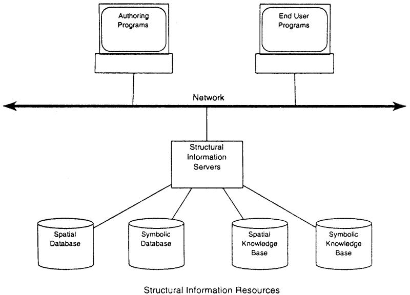
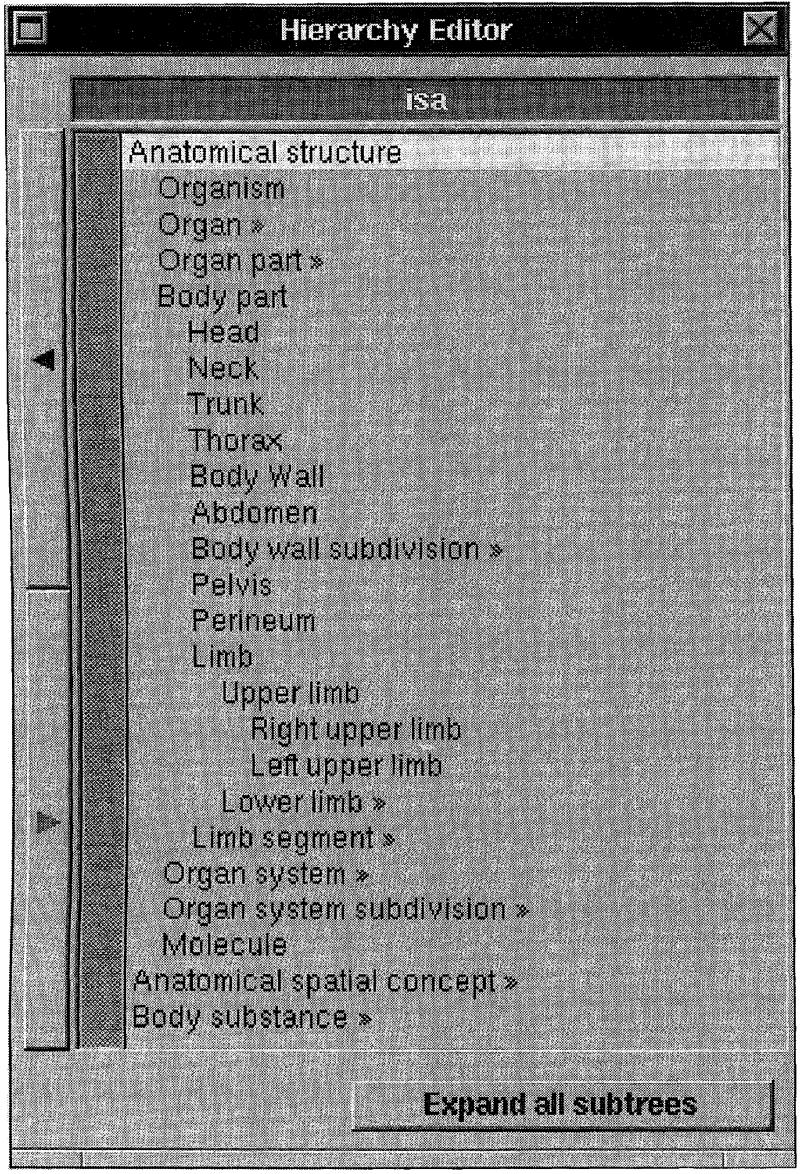
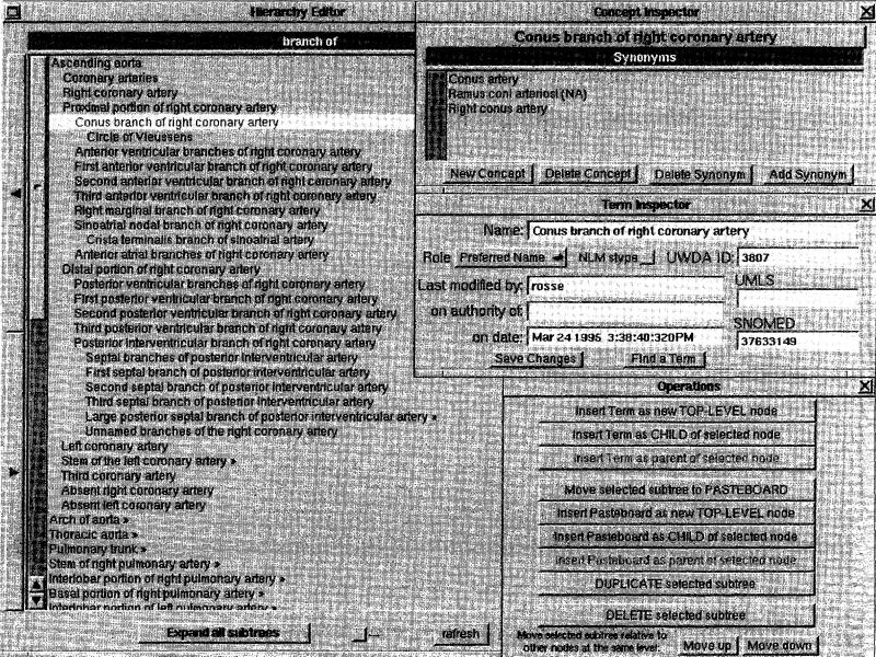
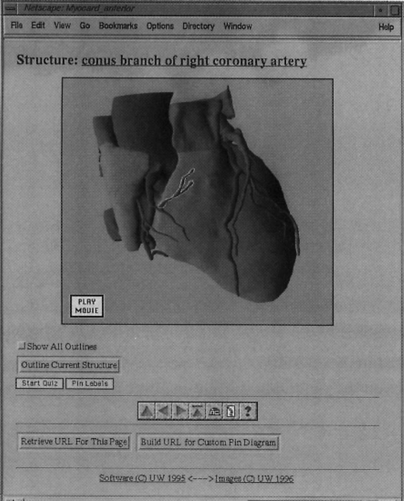
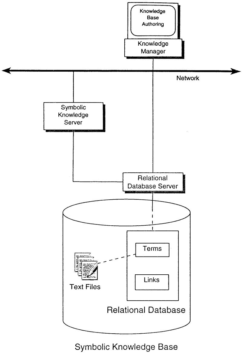
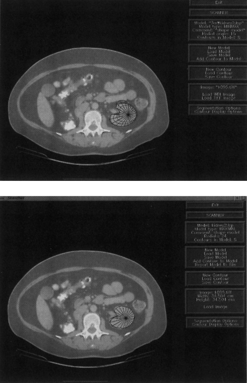
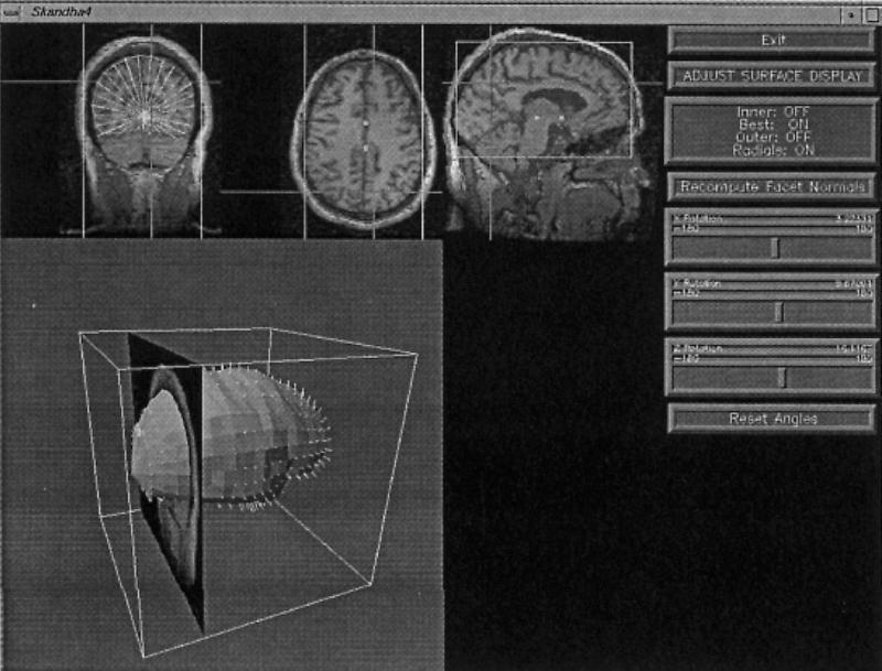
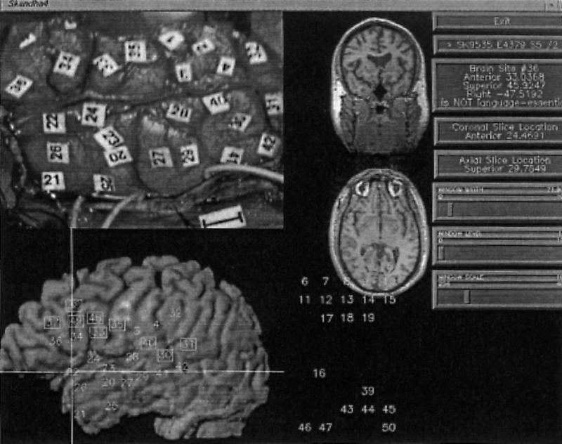
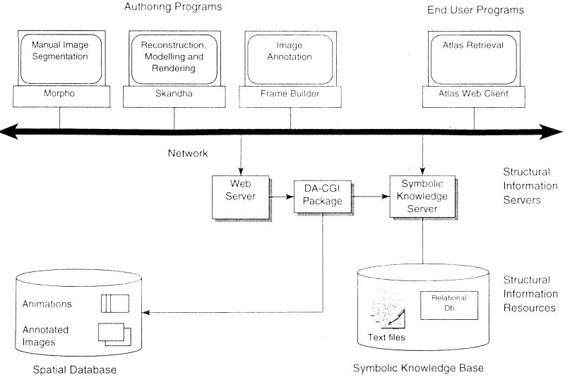
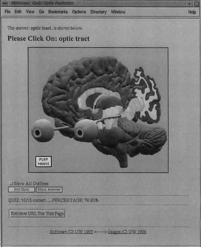
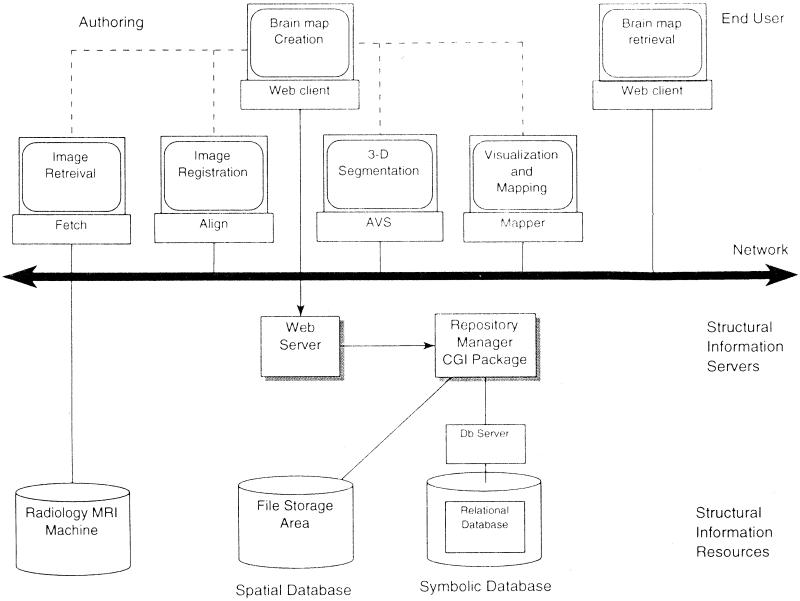
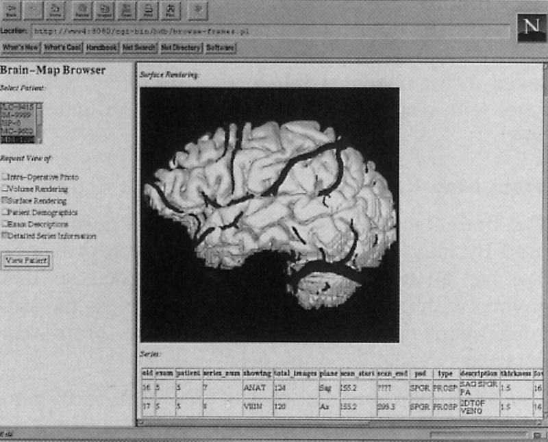
The domain of medical imaging is anatomy. Therefore, anatomic knowledge should be a rational basis for organizing and analyzing images. The goals of the Digital Anatomist Program at the University of Washington include the development of an anatomically based software framework for organizing, analyzing, visualizing and utilizing biomedical information. The framework is based on representations for both spatial and symbolic anatomic knowledge, and is being implemented in a distributed architecture in which multiple client programs on the Internet are used to update and access an expanding set of anatomical information resources. The development of this framework is driven by several practical applications, including symbolic anatomic reasoning, knowledge based image segmentation, anatomy information retrieval, and functional brain mapping. Since each of these areas involves many difficult image processing issues, our research strategy is an evolutionary one, in which applications are developed somewhat independently, and partial solutions are integrated in a piecemeal fashion, using the network as the substrate. This approach assumes that networks of interacting components can synergistically work together to solve problems larger than either could solve on its own. Each of the individual projects is described, along with evaluations that show that the individual components are solving the problems they were designed for, and are beginning to interact with each other in a synergistic manner. We argue that this synergy will increase, not only within our own group, but also among groups as the Internet matures, and that an anatomic knowledge base will be a useful means for fostering these interactions.


Figures

Figure 1
Figure 1
Conceptual architecture of the Digital Anatomist distributed framework. End user and authoring programs access a set of reusable structural information resources by means of one or more structural information servers. The resources are classified as data or knowledge, and as spatial or symbolic. Many of the research problems in structural informatics involve the development of representations for these resources.
Figure 2
Figure 2
Screen capture showing the three top level classes, and some of the subclasses, in our anatomical ontology. The » symbol indicates that the class has at least one subclass that is not shown. For example, “Organ” has 19 first-generation subclasses. The leaves of the tree are instances, as for example the “Right upper limb,” which belongs to the class “Upper limb.” Not all classes are yet instantiated (for example, “Molecule”).
Figure 4
Figure 4
Knowledge Manager. A NeXTStep program for entering new terminology and relationships in the Symbolic Knowledge Base. The left window shows the BRANCH-OF hierarchy for the Ascending Aorta. The conus branch of the right coronary artery is highlighted, and the corresponding concept and terms are shown in the upper right-hand windows. This concept is not in UMLS but is in SNOMED, and the preferred term has at least three synonyms.
Figure 8
Figure 8
Browse mode for the Web atlas client, showing an annotated 3-D image from our Thoracic Viscera atlas. The user has clicked in the outlined region, which caused the Web server to re-send the image with the name of the structure shown along the top. The user then clicked “Outline Current Structure,” causing the server to redraw the image with the current structure outlined. Other buttons include “Start Quiz,” which initiates Quiz mode (Fig. 9), and “Pin Labels,” which labels all the structures on the image. The row of buttons below the “Start Quiz” and “Pin Labels” buttons are for navigation, help and a table of contents. The bottom buttons generate URLs that can be pasted into on-line tutorials or syllabi. In the locally available version shown here, the user may click on the structure name to initiate a query to the Symbolic Knowledge Server. All processing is done by the server DA-CGI package.
Figure 3
Figure 3
Symbolic knowledge base management. The Symbolic Knowledge Base is a semantic network that is stored in the Terms and Links tables of a relational database. Attributes of the classes represented by the Terms are currently represented in associated text files. The database is accessed by a standard relational database server that is called directly by the Knowledge Manager knowledge acquisition program, Figure 4. The Knowledge Base can also be accessed by the Symbolic Knowledge Server, a hybrid Lisp-C application that provides a high level query language to the Knowledge Base.
Figure 5
Figure 5
F-2-D, shape-based image segmentation in the Scanner program. A: Initial 2-D radial contour model after user has indicated two endpoints, and constraints have propagated to generate an initial uncertainty region delineated by the inner and outer contours, and a bestguess contour as the midpoints along the radials in the uncertainty region. B: Final stage, after all edges have been found.
Figure 6
Figure 6
F-3-D, shape-based image segmentation in the Scanner program. A 3-D radial model is represented by a series of parallel slices, each of which is a 2-D radial model. Constraints relate not only radials on the same slice, but also neighboring slices, thereby allowing edges on one slice to constrain the search for edges on nearby slices. The top three panels are orthogonal views through a volume MR dataset of the brain. The bottom panel shows an instantiated model of the cerebral cortex after all radials have been found. The location of the current slice is shown in relation to the model.
Figure 10
Figure 10
Brain Mapper. Top left: intraoperative photo showing numbered stimulation sites. Bottom left: volume-rendered left temporal surface with mapped stimulation sites; square boxes are essential for language. Top middle: coronal and transverse slices through MR volume corresponding to intersection of lines shown on reconstruction. Bottom middle: palette of numbers that are dragged over the reconstruction to perform the mapping. Right: menu of operations.
Figure 7
Figure 7
Anatomy information system, as an instance of the conceptual framework shown in Figure 1. In this case the Spatial Database contains a series of anatomy atlases showing specific body regions, each consisting of 3-D animations and annotated images. The atlas contents are generated by the Morpho, Skandha, and Frame Builder authoring programs, and accessed via the Atlas Web client. All Web operations are controlled by the C-based DA-CGI Package, which also connects to the Symbolic Knowledge Server.
Figure 9
Figure 9
Quiz mode for the Web atlas client, showing an annotated 3-D image from our brain atlas. The DA-CGI programs systematically request the user to point to each annotated structure, keeping track of the number of correct answers. In this case the user has clicked “Show Answer,” which causes the server to redraw the image with the currently-request structure, optic tract, outlined. Hidden form items record the score and the list of structures already asked.
Figure 11
Figure 11
Brain map information system, as another instance of the conceptual framework shown in Figure 1. In this case images and other spatial data are saved in a protected “File Storage Area” of the Spatial Database, which is indexed by relational tables in the Symbolic Database. The combined data repository is managed by a Web based Repository Manager CGI package. The brain maps are created by a series of programs that are controlled by the Brain Map Creation Web client. One of these programs is Mapper, shown in Figure 10. The maps are retrieved by the Brain Map Retrieval Web client, one of whose screens is shown in Figure 12.
Figure 12
Figure 12
Brain Map Retrieval Web client. A Frames-based Web interface is used to display a list of patients in the left-hand frame. The user clicks to choose the patient and the list of items to be retrieved. When the “View Patient” button is pressed the repository manager formulates a query to the Msql database to retrieve the requested information, including the identifiers of image files in the spatial database. The results are packaged in the frame shown on the right, which in this case consists of a surface reconstruction with veins, and metadata about the MR image series.

Comment in

References

    1. Brinkley JF. Structural informatics and its applications in medicine and biology. Academic Medicine, 66: 589-91, 1991. - PubMed
    1. Rich E, Knight K. Artificial Intelligence. New York: McGraw-Hill, 2nd edition, 1991.
    1. Buchanan BG. Artificial intelligence as an experimental science. In: Aspects of Artificial Intelligence, Kluwer Academic Publishers, Dordrecht, Netherlands, 1988, pp. 209-50.
    1. Brinkley JF, Prothero JS, Prothero JW, Rosse C. A framework for the design of knowledge-based systems in structural biology. In 15th Annual Symposium on Computer Applications in Medical Care. New York: McGraw-Hill, 1989, pp. 61-5.
    1. Rosse C, Ben Said M, Eno KR, Brinkley JF. Enhancements of anatomical information in UMLS knowledge sources. In Gardner RM (ed.): 19th Annual Symposium on Computer Applications in Medical Care. Philadelphia, Hanley & Belfus, 1996, 873-7. - PMC - PubMed

Publication types

MeSH terms