. 1997 Aug;110(2):101-17.
doi: 10.1085/jgp.110.2.101.

Selectivity changes during activation of mutant Shaker potassium channels

Affiliations

Selectivity changes during activation of mutant Shaker potassium channels

J Zheng et al. J Gen Physiol. 1997 Aug.

Abstract

Mutations of the pore-region residue T442 in Shaker channels result in large effects on channel kinetics. We studied mutations at this position in the backgrounds of NH2-terminal-truncated Shaker H4 and a Shaker -NGK2 chimeric channel having high conductance (Lopez, G.A., Y.N. Jan, and L.Y. Jan. 1994. Nature (Lond.). 367: 179-182). While mutations of T442 to C, D, H, V, or Y resulted in undetectable expression in Xenopus oocytes, S and G mutants yielded functional channels having deactivation time constants and channel open times two to three orders of magnitude longer than those of the parental channel. Activation time courses at depolarized potentials were unaffected by the mutations, as were first-latency distributions in the T442S chimeric channel. The mutant channels show two subconductance levels, 37 and 70% of full conductance. From single-channel analysis, we concluded that channels always pass through the larger subconductance state on the way to and from the open state. The smaller subconductance state is traversed in approximately 40% of activation time courses. These states apparently represent kinetic intermediates in channel gating having voltage-dependent transitions with apparent charge movements of approximately 1.6 e0. The fully open T442S chimeric channel has the conductance sequence Rb+ > NH4+ > K+. The opposite conductance sequence, K+ > NH4+ > Rb+, is observed in each of the subconductance states, with the smaller subconductance state discriminating most strongly against Rb+.


Figures

Figure 1
Figure 1
Nomenclature of the mutations and comparison of their amino acid sequences. Dashes indicate residues identical to the sequence of Shaker. Expression of constructs was assayed by two-electrode voltage clamp. The constructs containing Cys, Asp, His, Val, and Tyr at position 442 failed to express ionic or gating currents when two batches of cRNA were injected into separate batches of oocytes. SS is based on the Shaker H4 construct, while SN and its derivatives were based on Shaker B, both with NH2-terminal truncations to remove fast inactivation.
Figure 2
Figure 2
Macroscopic currents from cell-attached patch recordings of the various channel types. (A) Activation currents were induced by depolarizing pulses from a −100-mV holding potential to potentials of: −50 to 100 mV (SN); −80 to 100 mV (SNS); −80 to 30 mV (SNG); and −80 to 60 mV (SS); all in steps of 10 mV except 20 mV for SNS. The post pulse was −140 mV. (B) Tail currents were recorded at voltages of −70 to −150 mV (SN) and −110 to −170 mV (SNS, SNG, and SS) after prepulses to 40 mV (SN) or 0 mV (SNS, SNG, and SS). Potassium ion concentration was 140 mM on each side of the patch. Currents were filtered at 1 kHz. Note the different time scale for SN currents. (C) Representative G-V curves for each channel type, calculated from the macroscopic currents assuming a linear I -V relationship. Superimposed on each curve is a fit of a Boltzmann function. The midpoint voltage V 1/2 and effective charge q for each channel type were −41.7 ± 2.7 mV, 5.1 ± 1.1 e0 (SN, n = 3); −66.3 ± 3.4 mV, 7.5 ± 1.2 e0 (SNS, n = 6); −87.9 ± 1.9 mV, 9.2 ± 0.8 e0 (SNG, n = 3); −66.8 ± 2.8 mV, 10.7 ± 1.6 e0 (SS, n = 4). (D) Voltage dependence of the activation time constant τa, estimated by fits of an exponential function to the activation time course, starting from the time when the amplitude is 50% of the final value. (E) Voltage dependence of the activation delay time δa obtained in the same fits as the time at which the extrapolated exponential crosses the current baseline. (F) Voltage dependence of deactivation time constants τd estimated by single-exponential fits. The apparent charge q was 0.80 e0 (SN), 0.96 e0 (SNS), 0.84 e0 (SNG), and 0.83 e0 (SS), as estimated by fitting the last five data points (lines) with the exponential function τ(V) = τ(0)exp(qV/kT).
Figure 3
Figure 3
Single-channel currents from five channel types, recorded in inside-out patches. (A) Representative single- chan-nel current traces of the SN channel and its derivatives. Potassium ion concentration was 140 mM on each side of the membrane. Channels were activated by a depolarization from a −100-mV holding potential to −60 mV (SN) or −70 mV (SNS and SNG). The tail potential was −140 mV (SN) or −120 mV (SNS and SNG). Note the different time scale for the SN current, which also has a larger single-channel conductance. Some dwells in subconductance levels are indicated by arrows. (B) Single-channel currents of Shaker and its derivative SS. Two selected sweeps recorded in symmetrical 140 mM K+ show the “nonbursting” and “bursting” behaviors of SS. The first sweep contains a brief dwell at a sublevel during activation (arrow) as well as a clear “staircase” of conductances during deactivation. Also shown are five successive sweeps from a truncated Shaker B channel, recorded with 5 mM external K+. Some dwells at subconductance levels are indicated by arrows. For the recording from the NH2-terminal–truncated Shaker B channel, the pipette solution contained 5 mM K-aspartate, 135 mM NMDG-aspartate, 1.8 mM CaCl2, and 10 mM Hepes. All recordings were filtered at 1 kHz. The recordings of SN and SS currents used uncoated patch pipettes, which yielded larger background noise.
Figure 4
Figure 4
First latencies of SN and SNS single-channel currents. (A and C) Representative traces at various depolarizations in single-channel patches from oocyte expressing SNS (A) or SN (C). The dotted line marks the beginning of the depolarizations. (B and D). The cumulative first-latency distributions are plotted for SNS (B) and SN (D) at the potentials indicated. First latencies were measured as the time to first opening, to either sub- or main conductance level.
Figure 5
Figure 5
Amplitudes of the three current levels in SNS channels. (A) Representative current trace showing channel activation at −70 mV and deactivation at −140 mV. Boxes indicate regions of this trace used in constructing the amplitude histograms. (B) Amplitude histograms of the single- channel current at the two voltages, accumulated from portions of 380 sweeps as in A. Filter bandwidth was 1 kHz. Superimposed are fits of three (−70 mV) or four (−140 mV) Gaussian functions; the midpoint of each Gaussian is taken to be the mean current amplitude. The standard deviations (in pA) of the Gaussian components are as follows. For −70 mV: 0.25 (closed), 0.36 (sub2), 0.25 (open); for −140 mV: 0.30 (closed), 1.0 (sub1), 0.54 (sub2), 0.50 (open). (C) The mean current amplitudes at different voltages. The superimposed linear fits yield the slope conductances shown.
Figure 6
Figure 6
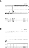
Sublevels of the SNS single-channel current during activation. (A) Representative traces at −70 mV. Solid lines show channel closed and open levels; dashed lines (θ1, θ2, and θ3) are thresholds at 10, 50, and 85% of the open amplitude. In the upper trace, the channel spends t 1 = 2.9 ms in the sub1 state and t 2 = 3.9 ms in the sub2 state before reaching the open state. In the lower trace, the channel appears to open instantaneously into sub2, but a finite t 1 is measured because of filtering. Filter bandwidth is 1 kHz. (B) Cumulative histogram of measured dwell times t 1 in sub1 (solid curve) accumulated from 140 events. The dashed curve is the cumulative distribution from a simulation of 250 events with mean lifetime τSub1 and fraction f Sub1 of nonzero dwells in sub1 as given. (C) A scheme for channel activation that accounts for the distributions of t 1 and t 2. Channels can open through two distinct pathways, allowing sub1 to be skipped but always traversing sub2. (D) Cumulative histogram of 140 dwell times at sublevel sub2. The dashed curve is from a simulation of 250 events with the given mean dwell time and fraction of nonzero dwells.
Figure 7
Figure 7
Examples of single-channel tail currents of SNS at −120 mV (A) and −140 mV (B). Solid lines show channel closed and open levels, while dashed lines indicate thresholds θ1, θ2, and θ3 at 10, 50, and 85% of the open level. Data filtered at 1 kHz. Below each trace is the idealized current time course.
Figure 8
Figure 8
Voltage dependence of mean dwell time in the open state and the two substates. Data points at each voltage represents the mean value, with the number of measurements marked in parentheses (except the data at −30 mV, which represents a single measurement). The curves are the values predicted from the kinetic scheme In Fig. 9.
Figure 9
Figure 9
Voltage dependence of transition rates. Rate constants were computed as described in Methods from single-channel activation time courses at −70 mV (n = 3 patches) and deactivation time courses at −100 (n = 2), −120 (n = 4), and −140 mV (n = 3). Superimposed on each plot is an exponential fit of the voltage dependence. The kinetic scheme (inset) summarizes the measurements from both activation and deactivation. Values for the rate constants (in s−1) are given for V = −120 mV. The partial valence associated with each rate constant is given in parentheses.
Figure 10
Figure 10
SNS single-channel currents with K+, NH4 +, or Rb+ as the permeant ions. (A) Single-channel currents recorded from inside-out patches, with 140 mM of the test ion in the pipette and 140 mM K+ in the bath. The voltage protocol is shown at the bottom. Note the small current in NH4 + at −60 mV, due to proximity to the reversal potential of −45 mV under these conditions. (B) Representative tail currents at −140 mV for each permeant ion. The open level is marked by an arrowhead. The S2′′ and S3′′ sublevels in Rb+ current are also indicated. (C) Amplitude histograms of tail currents at −140 mV for each permeant ion, accumulated from recordings filtered at 1 kHz. The data for K+ are the same as in Fig. 5 C; for NH4, the standard deviations of the fitted Gaussians are 0.1, 1.0, 0.9, and 1.1 pA for closed, sub1, sub2, and open levels, respectively. For Rb+, the standard deviations are 0.2 for the closed level, 0.6 for each sublevel, and 0.5 for the open level.
Figure 11
Figure 11
Solution switching experiment. (A) In an outside- out patch, the channel is activated by a depolarization to −70 mV from the −100-mV holding potential. Switching of the external solution occurs during the tail current at −120 mV, as shown by the dotted lines. In traces 1, 2, and 4, the K+ → Rb+ switching occurs while the channel is at the open level; in traces 3 and 5, it occurs while the channel is at sub2 sublevel. Trace 4 shows Rb+ → K+ switching while the channel is at sub2. Trace 6 shows Rb+ → K+ switching while the channel is at sub1. The pipette solution contained 130 mM K-aspartate, 10 mM KCl, 1 mM EGTA, 10 mM Hepes, and the bath solution contained 140 mM K-aspartate, 1.8 mM CaCl2, 10 mM Hepes; each was adjusted to pH 7.3. (B) Scatter plot of mean current values obtained before and after solution switching. Mean current was calculated only from the traces in which the current levels were stable for at least 5 ms both before and after the solution switching.
Figure 12
Figure 12
Amplitudes of each current level in SNS channels at −120 mV when K+, NH4 +, or Rb+ is the external ion.
Figure 13
Figure 13
Two speculative gating schemes. (A) The scheme of Zagotta et al. (1994b) is shown, in which a single subunit undergoes two voltage-dependent conformational transitions (inset) to reach a permissive state (circles). Subunit transitions occur independently, with the exception of a slowed transition from the open state 14 to state 13. The scheme has been modified to identify sublevels sub1 and sub2 with states in which two or three subunits are in the permissive state. (B) The scheme Is modified to include a distinct allosteric transition (dotted line) that follows activation of the subunits. The allosteric transition is assumed to be very rapid and switches between fully conducting and nonconducting states. Allosteric equilibria are influenced by a common factor θ that is greatly increased by the T442S mutation. In both schemes, the conducting states are represented by filled symbols.

Similar articles

Cited by

References

    1. Bezanilla F, Armstrong CM. Inactivation of the sodium channel. I. Sodium current experiments. J Gen Physiol. 1977;70:549–566. - PMC - PubMed
    1. Bezanilla F, Perozo E, Stefani E. Gating of Shaker K+channels: II. The components of gating currents and a model of channel activation. Biophys J. 1994;66:1011–1021. - PMC - PubMed
    1. Blumenthal EM, Kaczmarek LK. Modulation by cAMP of a slowly activating potassium channel expressed in Xenopusoocytes. J Neurosci. 1992;12:290–296. - PMC - PubMed
    1. Brown AM. Functional bases for interpreting amino acid sequences of voltage dependent K channels. Annu Rev Biophys Biomol Struct. 1993;22:173–198. - PubMed
    1. Chapman ML, VanDongen HMA, VanDongen AMJ. Activation-dependent subconductance levels in the drk1 K channel suggest a subunit basis for ion permeation and gating. Biophys J. 1997;72:708–719. - PMC - PubMed

Publication types