. 1997 Oct 20;139(2):397-415.
doi: 10.1083/jcb.139.2.397.

Analysis of the actin-myosin II system in fish epidermal keratocytes: mechanism of cell body translocation

Affiliations

Analysis of the actin-myosin II system in fish epidermal keratocytes: mechanism of cell body translocation

T M Svitkina et al. J Cell Biol. .

Abstract

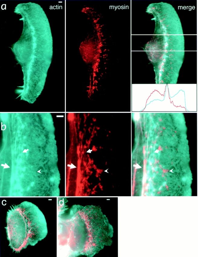
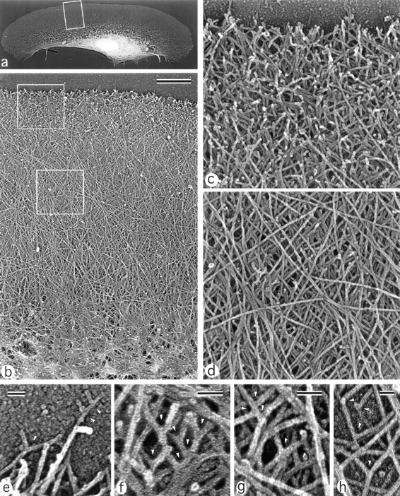
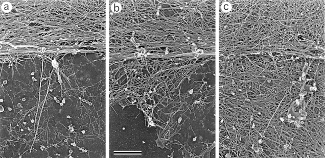
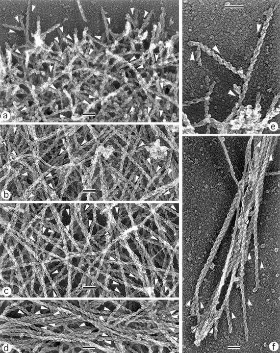
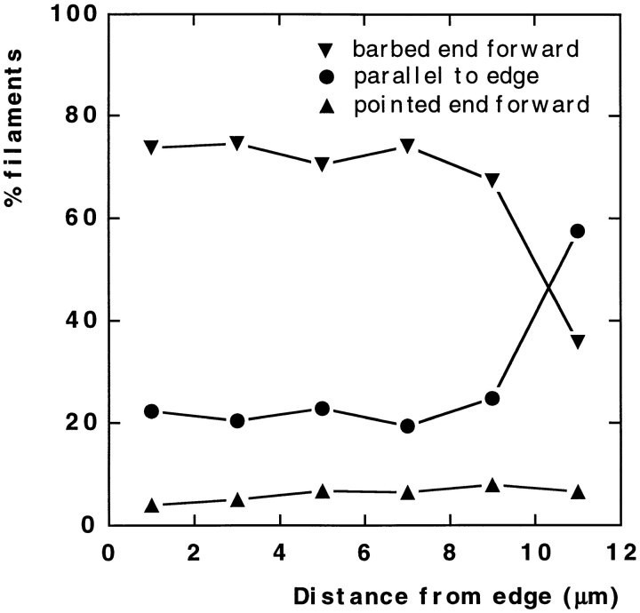
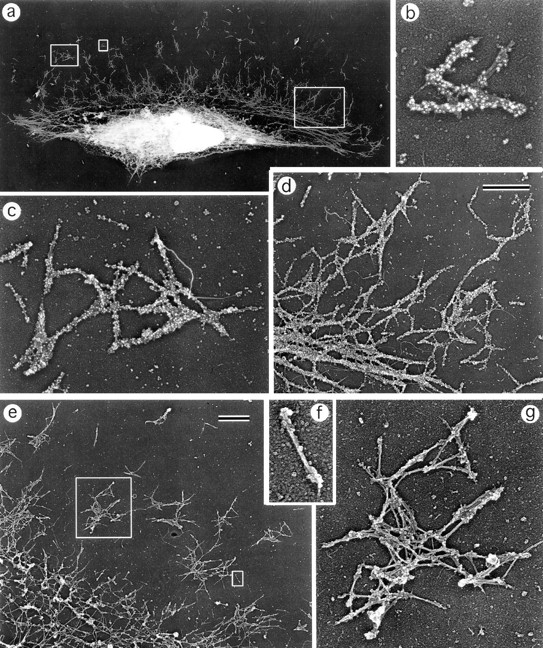
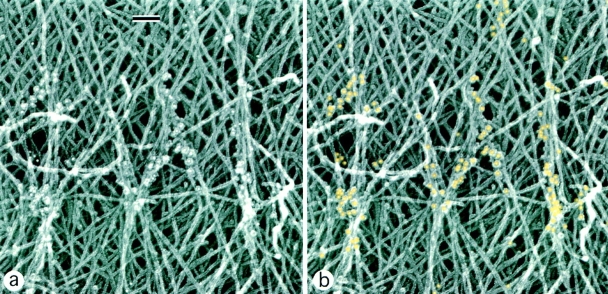
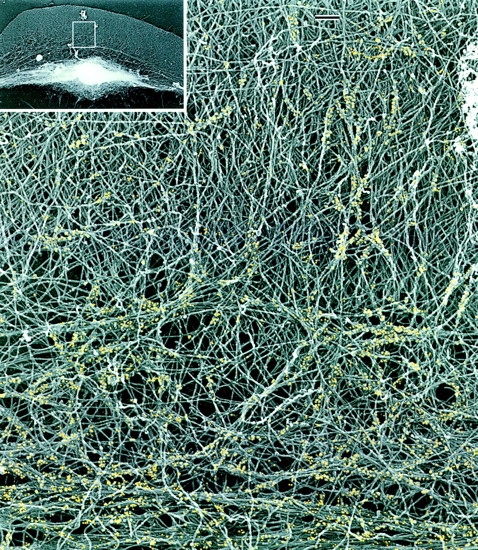
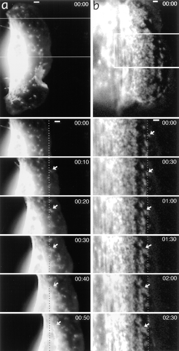
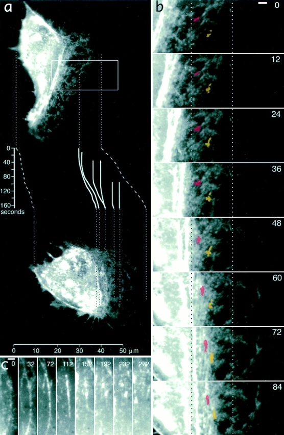
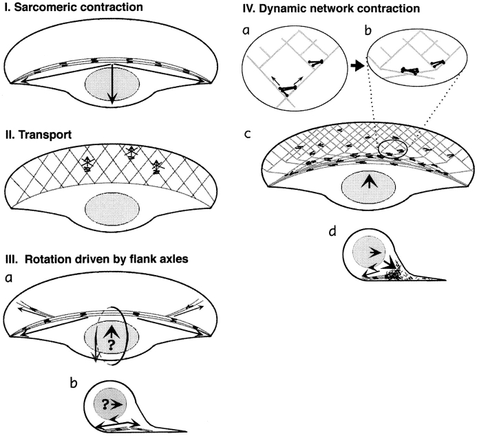
While the protrusive event of cell locomotion is thought to be driven by actin polymerization, the mechanism of forward translocation of the cell body is unclear. To elucidate the mechanism of cell body translocation, we analyzed the supramolecular organization of the actin-myosin II system and the dynamics of myosin II in fish epidermal keratocytes. In lamellipodia, long actin filaments formed dense networks with numerous free ends in a brushlike manner near the leading edge. Shorter actin filaments often formed T junctions with longer filaments in the brushlike area, suggesting that new filaments could be nucleated at sides of preexisting filaments or linked to them immediately after nucleation. The polarity of actin filaments was almost uniform, with barbed ends forward throughout most of the lamellipodia but mixed in arc-shaped filament bundles at the lamellipodial/cell body boundary. Myosin II formed discrete clusters of bipolar minifilaments in lamellipodia that increased in size and density towards the cell body boundary and colocalized with actin in boundary bundles. Time-lapse observation demonstrated that myosin clusters appeared in the lamellipodia and remained stationary with respect to the substratum in locomoting cells, but they exhibited retrograde flow in cells tethered in epithelioid colonies. Consequently, both in locomoting and stationary cells, myosin clusters approached the cell body boundary, where they became compressed and aligned, resulting in the formation of boundary bundles. In locomoting cells, the compression was associated with forward displacement of myosin features. These data are not consistent with either sarcomeric or polarized transport mechanisms of cell body translocation. We propose that the forward translocation of the cell body and retrograde flow in the lamellipodia are both driven by contraction of an actin-myosin network in the lamellipodial/cell body transition zone.


Figures

Figure 1
Figure 1
Localization of actin and myosin II in keratocytes by fluorescence microscopy. Actin (cyan) and myosin (red) distributions are revealed by TRITC-phalloidin and indirect immunofluorescence staining, respectively. Overall actin and myosin II organization in a typical wing-shaped locomoting cell (a), enlarged portion of another cell exhibiting various patterns of actin and myosin mutual arrangement (b), locomoting cell of a symmetrical shape (c), and a tethered cell (d) are shown. All cells exhibit discrete myosin spots among continuous actin network in lamellipodia, as well as accumulation of both actin and myosin at the lamellipodia/cell body boundary. Intensity profiles of actin (cyan) and myosin (red) within the cell area indicated in the “merge” panel of a are shown in the inset, and they illustrate reverse gradients of actin and myosin in lamellipodia. (b) Examples of a myosin spot in the lamellipodia that does not coincide with any discrete actin structure (arrowhead), myosin spots coinciding with small actin bundles merging to boundary bundles (small arrow), and colocalization of actin and myosin in the boundary bundle (large arrow). Bars, 2 μm.
Figure 2
Figure 2
Organization of actin filaments in keratocyte lamellipodia. EM of detergent-extracted cells. (a) Overview of a locomoting cell; (b) actin network in lamellipodia from the leading edge (top) to the transitional zone (bottom); (c) brushlike zone at the leading edge with numerous filament ends; (d) smooth actin filament network in the middle part of lamellipodia; (e–h), T junctions (arrowheads) between filaments at the extreme leading edge (e), within the brushlike zone (f), in the central lamellipodia (g), and close to the lateral edge of the lamellipodia (h). The cell's leading edge is oriented upward in all panels. Boxed region in a is enlarged in b; upper and lower boxed regions in b are enlarged in c and d, respectively. Bars: (b) 1 μm; (e–h) 50 nm.
Figure 3
Figure 3
Organization of actin filaments in the lamellipodia–cell body transition zone. EM of wet-cleaved cells with nuclei removed shows actin bundles in the transition zone (top of each panel) and a network of actin filaments at the bottom of the cell body (bottom of each panel). Different amounts of actin filaments remain associated with bottom plasma membrane (a–c). Orientation of actin filaments is random (a and b) or approximately parallel to the transition zone bundle (c). The cell's leading edge is oriented upward in all panels. Bar, 0.1 μm.
Figure 4
Figure 4
Polarity of actin filaments in keratocyte cytoskeleton. EM of detergent-extracted cells after myosin S1 decoration. (a) Leading edge; (b) middle portion of a lamellipodium; (c) transitional zone; (d) boundary bundle; (e) T junctions between actin filaments at the leading edge; (f) retraction fiber at the cell rear. Directions of pointed ends of some filaments are shown by arrowheads located next to a filament. Filaments are oriented primarily with barbed end forward throughout the lamellipodia (a–c), while the boundary bundle has mixed filament polarity (d). At T junctions, filaments are oriented with pointed end toward the junction (e). The retraction fiber (f) contains uniformly oriented filaments with their barbed ends to the tip of the fiber. Unlabeled intermediate filaments can be seen in some panels. The cell's leading edge is oriented upward in all panels. Bars, 0.1 μm.
Figure 5
Figure 5
Quantitation of actin filament polarity in keratocyte lamellipodia. Polarity of filament orientation was determined with respect to the leading edge as being in one of three categories (see Materials and Methods): barbed end forward, pointed end forward, or parallel to the edge. Determinations were made in cells of similar size and morphology, covering the whole width of the lamellipodia, within 2-μm zones parallel to the leading edge, and for a depth of 12 μm behind the leading edge. A total of 3,761 filaments were scored in five cells, converted to percentage per cell, and the mean percentages were plotted against distance from the leading edge. The percentage of filaments in each category remained constant throughout the lamellipodia (0–8 μm) until the transitional zone was reached (8–12 μm).
Figure 6
Figure 6
Organization of myosin II filaments in keratocytes. EM of detergent-extracted and gelsolin-treated cells with (a–d) or without (e–g) myosin immunogold labeling. (a) Overview of a cell; (b and c) clusters of gold-labeled myosin filaments; (d) gold-labeled myosin filament network (upper right) that gradually transforms into boundary bundle (lower left); (e) part of a cell without labeling; (f) individual myosin bipolar filament; (g) cluster of myosin bipolar filaments associated predominantly at their heads. The cell's leading edge is oriented upward in all panels. Left, middle, and right boxed regions in a are enlarged in b–d, respectively. Small and large boxed regions in e are enlarged in f and g, respectively. Bars, 1 μm.
Figure 7
Figure 7
Relative distribution of actin and myosin II filaments in keratocyte lamellipodia. EM of detergent-extracted cells after myosin immunogold labeling shows a few myosin filaments (revealed as rod-shaped groups of gold particles) among actin filaments. Actin filaments contacting myosin tend to be arranged into small bundles. b Same image as a, but with gold particles digitally colorized in yellow. The cell's leading edge is oriented upward. Bars, 0.1 μm.
Figure 8
Figure 8
Relative distribution of actin and myosin II filaments in the keratocyte lamellipodia–cell body transition zone. EM of a detergent-extracted cell (overview in inset) after myosin immunogold labeling shows myosin filament clusters and the boundary bundle (bottom) within an actin filament network. Actin filaments forming small bundles and changing their course can be seen at sites of myosin localization. For better visualization, gold particles are digitally colorized in yellow. Bars, 0.2 μm.
Figure 9
Figure 9
Myosin spots are stationary in the lamellipodia of a locomoting keratocyte (a), but they exhibit retrograde flow in the lamellipodia of a tethered cell (b). General views of tetramethylrhodamine-myosin–injected cells and time-lapse sequences for boxed areas are shown with time indicated in minute and seconds. Dotted lines indicate fixed positions with respect to the substratum. Selected myosin spots are shown with arrows. In a, the marked myosin spot is stationary while in the lamellipodia, but exhibits forward displacement at 50 s when it reaches the cell body. Bars, 2 μm.
Figure 10
Figure 10
Formation of myosin bundles in the lamellipodia–cell body transition zone of a locomoting keratocyte is associated with forward translocation of myosin features. (a) An overview of a keratocyte at the start of observation (top) and after 168 s (bottom). Positions of two images reflect actual displacement of the cell in the horizontal direction. Traces of the cell's leading and rear edges (dashed lines) and selected myosin features (solid lines) are shown in the inset with time indicated in seconds on the vertical scale. One of the myosin spots traced is visible on the image at time 0, others have arisen at later time points and ended up, depending on time of their appearance and initial position, in the lamellipodium, in the lamellipodia–cell body transition zone, and as part of contracted myosin aggregates in the cell body at 168 s. Traces illustrate that myosin spots are initially stationary but become sequentially involved in forward translocation as the cell advances. (b) Details of bundle formation in the cell region indicated with box in a. Two myosin spots are highlighted with red and yellow. Dotted lines indicate positions fixed with respect to the substratum. Myosin spots are compressed in a horizontal direction (direction of locomotion), resulting in bundle formation and displacement to the right (forward). (c) The fate of a small myosin bundle as it forms at the cell body boundary (time 0) and contracts (112 s), fragments (152–232 s), and disappears (272 s) within the cell body. Bars, 2 μm.
Figure 11
Figure 11
Models of cell body translocation. Actin filaments are shown as gray lines, and myosin filaments are shown as black lines or dumbbell figures. (I) The sarcomeric mechanism cannot drive the cell body forward because arc-shaped actin– myosin II bundles, upon contraction, would produce a backward-directed net force on the cell body. (II) The transport model does not fit the data because myosin clusters in the lamellipodia, the only part of a cell where transport tracks are present, do not move forward. (III) Forward rolling driven by actin–myosin axles seems problematic because of the predominantly backward orientation of flanking bundles (a, top view). These bundles may participate in rolling by exerting a rearward-directed force at the bottom (b, vertical section); however, the origin of forward-directed force remains unclear (question mark). (IV) According to the dynamic network model, contraction of an actin–myosin network in the lamellipodia– cell body transition zone is coupled to forward translocation. (a) In the lamellipodium, the network of divergent actin filaments interacts with clusters of myosin bipolar filaments. Whereas small myosin clusters situated in the dense network close to cell front cannot move, bigger clusters in the sparser network in the transition zone are capable of approaching the barbed ends of diverging filaments and moving forward. (b) As myosin clusters move forward, they align actin filaments parallel to the leading edge. (c) Overall, network contraction at the lamellipodia–cell body transition zone results in formation of actin–myosin bundles and forward translocation of the cell body. (d) Vertical section view shows that forward rolling would result from a combination of network contraction in front of the cell body with rearward drag resulting from actin–myosin bundles at the bottom of the body.

References

    1. Anderson KI, Wang Y-L, Small JV. Coordination of protrusion and translocation of the keratocyte involves rolling of the cell body. J Cell Biol. 1996;134:1209–1218. - PMC - PubMed
    1. Begg DA, Rodewald R, Rebhun LI. The visualization of actin filament polarity in thin sections: evidence for the uniform polarity of membrane associated filaments. J Cell Biol. 1978;79:846–852. - PMC - PubMed
    1. Brands R, Feltkamp CA. Wet cleaving of cells: a method to introduce macromolecules into the cytoplasm. Application for immunolocalization of cytosol-exposed antigens. Exp Cell Res. 1988;176:309–318. - PubMed
    1. Byers, H.R., G.E. White, and K. Fujiwara. 1984. Organization and function of stress fibers in cells in vitro and in situ. In Cell and Muscle Motility. Vol. 5. J.W. Shay, editor. Plenum Publishing Corp., New York. 83–137. - PubMed
    1. Carlier M-F, Laurent V, Santolini J, Melki R, Didry D, Xia G-X, Hong Y, Chua N-H, Pantaloni D. Actin depolymerizing factor (ADF/cofilin) enhances the rate of filament turnover: implication in actin-based motility. J Cell Biol. 1997;136:1307–1323. - PMC - PubMed

Publication types