. 1998 Oct 15;18(20):8402-16.
doi: 10.1523/JNEUROSCI.18-20-08402.1998.

Directional tuning of single motor units

Affiliations

Directional tuning of single motor units

U Herrmann et al. J Neurosci. .

Abstract

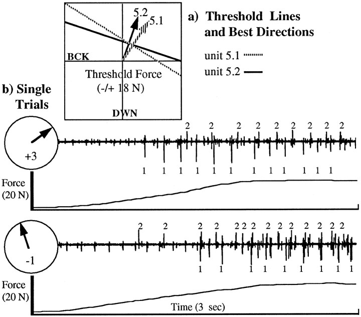
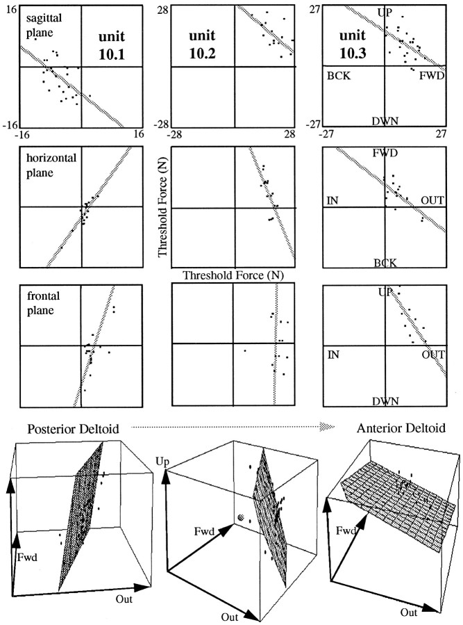
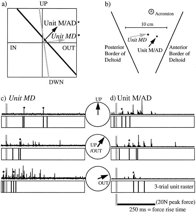
The directional activity of whole muscles has been shown to be broadly and often multimodally tuned, raising the question of how this tuning is subserved at the level of single motor units (SMUs). Previously defined rules of SMU activation would predict that units of the same muscle (or at least of the same neuromuscular compartment) are activated homogeneously with activity peaks in the same "best" direction(s). In the present study, the best directions of SMUs in human biceps (both heads) and deltoid (anterior, medial, and posterior portions) were determined by measuring the firing rate and threshold force of units for recruitment during isometric force ramps in many different directions. For all muscles studied, neighboring motor units could have significantly different best directions, suggesting that each muscle receives multiple directional commands. Furthermore, 17% of the units sampled clearly had a second-best direction, consistent with a convergence of different directional commands onto the same motoneuron. The best directions of the units changed gradually with location in the muscle. Best directions did not cluster into separate groups, thus, not supporting the existence of clearly distinguished neuromuscular compartments. Instead, the results reveal a more gradually distributed activation of the biceps and deltoid motoneuron pools. A model is proposed in which the central control mechanism optimizes the fulfillment of the continuously changing directional force requirements of a movement by gradually recruiting and derecruiting those units ideally suited for the production of the required force vector at any given time.


Figures

Fig. 1.
Fig. 1.
a, Distribution of targets. First set of experiments: subjects produced isometric forces in 20 different directions covering the sagittal (UpBack) plane. Second set: subjects produced forces in 54 different directions covering the sagittal (UpBack), horizontal (BackOut), and frontal (UpOut) planes. b, Subject B, sagittal plane: 120 force traces (6 per direction) from four different experiments. Force traces stay close to the sagittal plane, especially those in the up and forward directions. c, Typical force trace (I), unit record (II), and unit raster (III). Threshold force is marked in force trace with a gray line. Close-up below unit trace shows consistent shape and amplitude of the potential of this unit.
Fig. 2.
Fig. 2.
Hypothetical, perfectly cosine-tuned unit with its best direction (arrows) straight up. a, Cosine-tuned firing frequency. In the right triangle, firing ratef is equal to the cosine of the angle φ.b, Inversely cosine-tuned threshold force. In the right triangle the threshold force t is equal to 1/cosφ.c, Relation between threshold force and firing frequency. Threshold force is minimal for directions in which firing frequency is maximal and vice versa. d, The fact that threshold data in 2D can be fit by a line is consistent with a model in which 3D threshold data fall on a plane, and the best direction of the unit is given by the direction of shortest (i.e., perpendicular) distance between the plane and the origin (straight up arrow).
Fig. 3.
Fig. 3.
Directional activity tuning plots for whole muscles as measured with surface EMG. BI activity is broadly tuned and can be fit by a single cosine function. Data from PD can be best fit by two cosine functions with nearly opposite peaks (two circles with two arrows). Partially because of the sampling bias inherent in multiunit surface EMG, it is not clear exactly how these tuning curves correspond to the tuning of the individual motor units. All data are from subject B.
Fig. 4.
Fig. 4.
Threshold force at recruitment and firing rate at steady state vary systematically with the direction of force at the wrist. a, Posture of the arm (side view) during the experiments. b, All unit recordings are aligned with force rise onset (marked by arrowhead below traces) and were recorded from one BI electrode during the same experiment. Three trials are shown for each direction; the presentation order was randomized during the experiment. As force direction changes from +1 to +3, and from 0 to −2, the force levels at recruitment become progressively higher, whereas firing rate at steady state decreases.c, Typical force trajectory with onset of force rise marked by the arrowhead. The vertical scale bar represents 20 N. d, Threshold force data plotted in y/x coordinates are fit by a line whose perpendicular (arrow) points in the best direction of the unit.
Fig. 5.
Fig. 5.
Recruitment reversal with force direction. Units 1 and 2 found on the same electrode had different preferred directions (arrows) as shown in a and were recruited in a different order depending on the force direction.b, For a force ramp in an up–forward direction, unit 1 was recruited before unit 2. For the force ramp in an up–backward direction, unit 2 was recruited before unit 1.
Fig. 6.
Fig. 6.
Threshold lines and frequency data for units in biceps. Best directions as found from the threshold line or the cosine fit are marked by arrows. Units 1 and 2 had significantly different preferred directions. Unit 3 showed more than one preferred direction. Action potential waveforms for unit 3 are shown for trials in the two lobes of activation. All data are from subject B. Bimodally tuned activity was seen in 29% of the biceps units pooled across all subjects.
Fig. 7.
Fig. 7.
Relation between the best direction of a unit and its location in BI. a, Best directions as found from the threshold line fit plotted against location in the muscle for each individual subject. The two preferred directions of a bidirectional unit are marked with a star for the best direction and an open circle for the second-best direction. Regressing only the best direction (for unimodally and bimodally tuned units) on location in the muscle yielded a significant correlation in subject B only. b, Pooling data from all subjects by normalizing recording location yielded a significant correlation between best direction and location (p < 0.005). This relation suggests that units located laterally and medially are best activated for upward and up–forward forces, respectively. (For simplicity, only the best direction is shown for each unit in the first plot. In the second plot, the second-best directions are included.)c, Map of biceps with recording sites in all subjects. Sites of electrode insertion for a particular subject are marked with a corresponding letter.
Fig. 8.
Fig. 8.
Distribution of best directions of units in BI.Bars of histograms denote bins of 18°, the angular separation between experimental targets. Superimposed on one histogram is the “continuous” (bin width of 1°) distributions of best directions. a, Distribution of best directions as found from the threshold line. Data are pooled from all subjects and include only the best direction. Three clusters were found as marked in the histogram by horizontal, dashed lines. The second plot shows the distribution of units of each group in the muscle. Members of a group were not constrained to a specific area in BI. b, Distribution of best directions (pooled data) as found from the direction of minimum threshold force. Note the wider range of best directions when compared with that ofa.
Fig. 9.
Fig. 9.
Threshold lines for units in deltoid. Best directions as found from the threshold line are marked byarrows. Units 1 and 2 had nearly opposite preferred directions. Units 3–5 showed more than one preferred direction. Action potential waveforms for units 3–5 are shown for trials in the different quadrants of activation.
Fig. 10.
Fig. 10.
Threshold lines and planes for deltoid units 1 (most posterior) to 3 (most anterior). The top three rows show the threshold lines in each plane derived from trials with force ramps within the respective plane. For the plots in thebottom row, data from all trials were combined in 3D and fit by a plane. The origin of the plot is located at the center of the cube and is marked by the small sphere in the plot for unit 2. The equations for the plane fits are as follows: unit 1,z = −2196.3 + 7.4x − 2.8y; unit 2, z = 7628.3 − 3.4x − 1.9y; unit 3,z = 1245.6 − 0.4x− 0.3y, where x, y, andz have positive values for outward, forward, and upward, respectively. As location of the units changes from posterior to anterior, the best direction appears to “jump” from down–backward to up–forward in the sagittal plane; in the horizontal and frontal planes, however, it appears to gradually rotate counterclockwise from out–back to out–forward and from out–down to out–up. All data are from subject A.
Fig. 11.
Fig. 11.
Threshold lines (top) and planes (bottom) for a deltoid unit with two preferred directions. The origin of the plot is located in the center of the polygon. From only the sagittal plane data, it might be assumed that the two threshold planes are parallel and the two best directions 180° apart. Data in the other two planes show, however, that the two threshold planes have a line of intersection.
Fig. 12.
Fig. 12.
a, 3D best direction of each unit versus their locations in deltoid, for each subject. The best direction is given by the direction of the unit vector from the origin. The color of the vector codes for location. As location changes from posterior to anterior (and color changes from the blue to thered end of the spectrum), best direction changes from down–out–backward to up–out–forward. b, Pooled 3D best directions of all units versus their normalized locations in deltoid, for all subjects. Best directions are coded for location as ina.
Fig. 13.
Fig. 13.
Dynamic pulses in the frontal plane; relative timing of two deltoid units with different best directions.a, Threshold lines of unitsM/AD (medial/anterior deltoid) andMD (medial deltoid) in the frontal plane.b, Locations of these units. Note that the more anterior unit has a best direction with a greater upward component than that of the more medial unit. c, MD rectified multiunit records for one trial and unit rasters for three trials in each direction (note that the unit potential could not always be recognized because of firing of other units). As the direction of the pulse changed from up to up–out, the bursts were earlier with respect to force onset (gray line). d, Simultaneously recorded EMG from M/AD exhibits the opposite temporal relation to force onset.

References

    1. Buchanan TS, Almdale DPJ, Lewis JL, Rymer WZ. Characteristics of synergic relations during isometric contractions of human elbow muscles. J Neurophysiol. 1986;56:1225–1241. - PubMed
    1. Buneo CA, Boline J, Soechting JF, Poppele RE. On the form of the internal model for reaching. Exp Brain Res. 1995;104:467–479. - PubMed
    1. Buneo CA, Soechting JF, Flanders M. Postural dependence of muscle actions: implications for neural control. J Neurosci. 1997;17:2128–2142. - PMC - PubMed
    1. Burke RE. Motor unit types of cat triceps surae muscle. J. Physiol (Lond) 1967;193:141–160. - PMC - PubMed
    1. Carrasco DI, English AW. Parts of cat biceps femoris produce different mechanical actions about the ankle and knee. Soc Neurosci Abstr. 1997;23:2097.

Publication types

LinkOut - more resources