

Short-term memory for reaching to visual targets: psychophysical evidence for body-centered reference frames
- PMID: 9763485
- PMCID: PMC6792850
- DOI: 10.1523/JNEUROSCI.18-20-08423.1998
Short-term memory for reaching to visual targets: psychophysical evidence for body-centered reference frames
Abstract
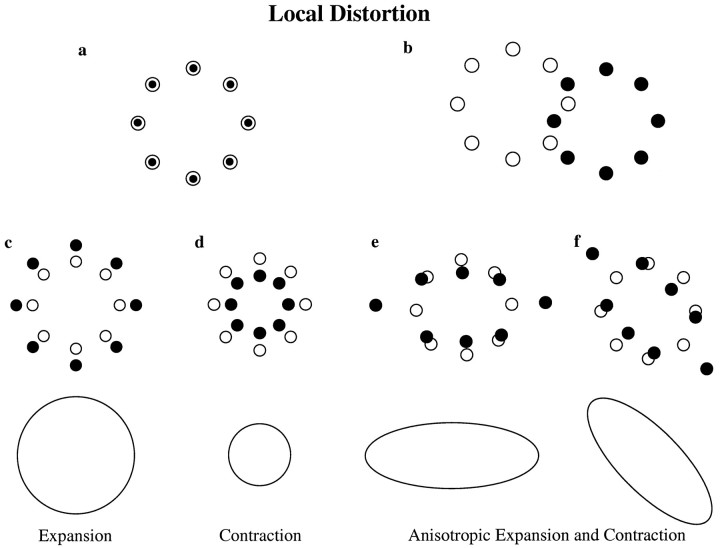
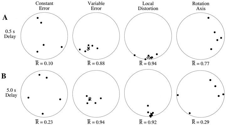
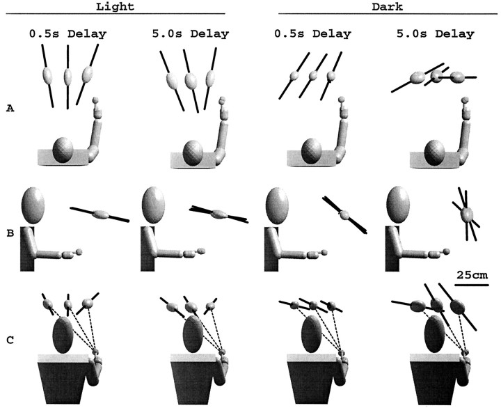
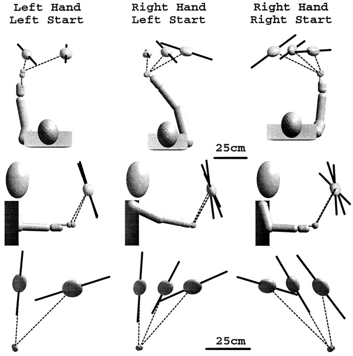
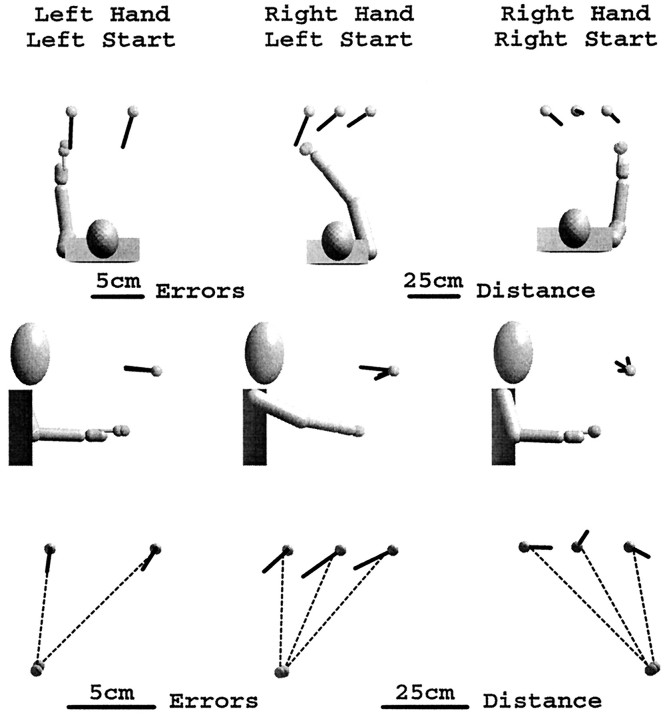
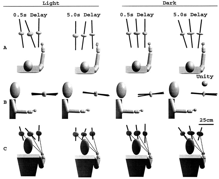
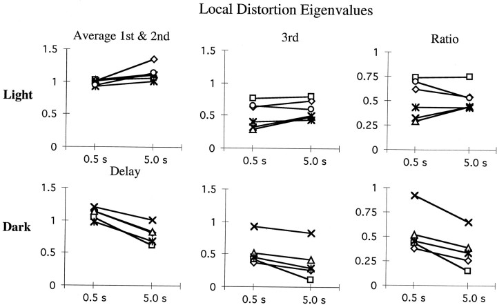
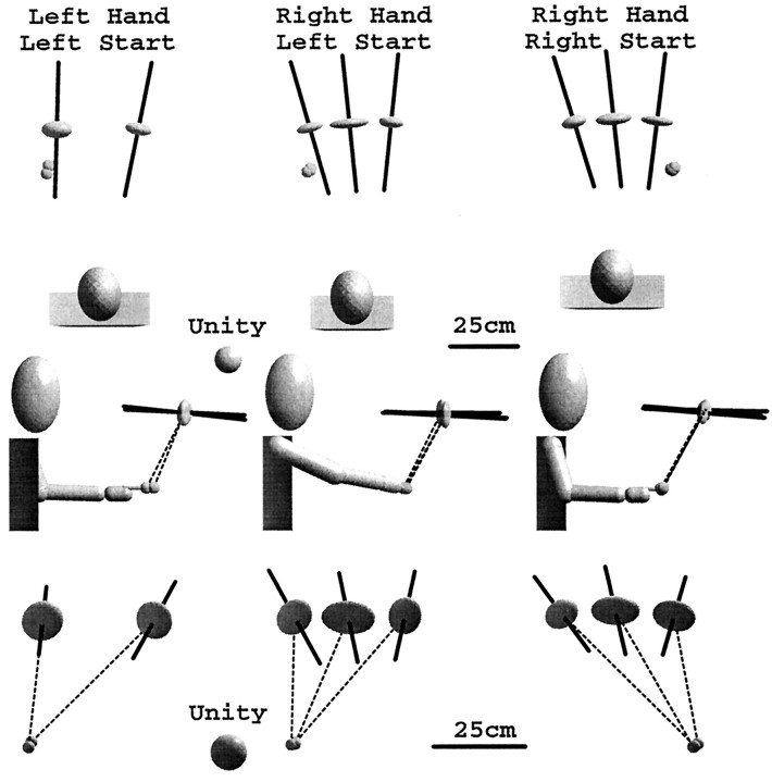
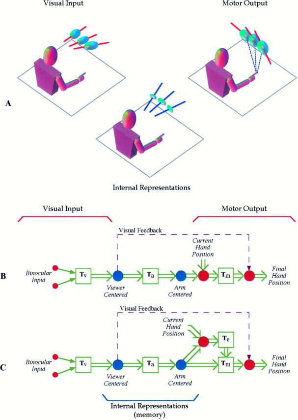
Pointing to a remembered visual target involves the transformation of visual information into an appropriate motor output, with a passage through short-term memory storage. In an attempt to identify the reference frames used to represent the target position during the memory period, we measured errors in pointing to remembered three-dimensional (3D) targets. Subjects pointed after a fixed delay to remembered targets distributed within a 22 mm radius volume. Conditions varied in terms of lighting (dim light or total darkness), delay duration (0.5, 5.0, and 8.0 sec), effector hand (left or right), and workspace location. Pointing errors were quantified by 3D constant and variable errors and by a novel measure of local distortion in the mapping from target to endpoint positions. The orientation of variable errors differed significantly between light and dark conditions. Increasing the memory delay in darkness evoked a reorientation of variable errors, whereas in the light, the viewer-centered variability changed only in magnitude. Local distortion measurements revealed an anisotropic contraction of endpoint positions toward an "average" response along an axis that points between the eyes and the effector arm. This local contraction was present in both lighting conditions. The magnitude of the contraction remained constant for the two memory delays in the light but increased significantly for the longer delays in darkness. These data argue for the separate storage of distance and direction information within short-term memory, in a reference frame tied to the eyes and the effector arm.
Figures
Similar articles
-
Viewer-centered frame of reference for pointing to memorized targets in three-dimensional space.J Neurophysiol. 1997 Sep;78(3):1601-18. doi: 10.1152/jn.1997.78.3.1601. J Neurophysiol. 1997. PMID: 9310446 Clinical Trial.
-
Multiple frames of reference for pointing to a remembered target.Exp Brain Res. 2005 Jul;164(3):301-10. doi: 10.1007/s00221-005-2249-2. Epub 2005 Mar 22. Exp Brain Res. 2005. PMID: 15782349
-
The interaction of visual and proprioceptive inputs in pointing to actual and remembered targets in Parkinson's disease.Neuroscience. 2001;104(4):1027-41. doi: 10.1016/s0306-4522(01)00099-9. Neuroscience. 2001. PMID: 11457588
-
Is reaching eye-centered, body-centered, hand-centered, or a combination?Rev Neurosci. 2001;12(2):175-85. doi: 10.1515/revneuro.2001.12.2.175. Rev Neurosci. 2001. PMID: 11392457 Review.
-
The coding and updating of visuospatial memory for goal-directed reaching and pointing.Vision Res. 2011 Apr 22;51(8):819-26. doi: 10.1016/j.visres.2011.01.006. Epub 2011 Jan 13. Vision Res. 2011. PMID: 21237190 Review.
Cited by
-
Medication improves velocity, reaction time, and movement time but not amplitude or error during memory-guided reaching in Parkinson's disease.Physiol Rep. 2024 Sep;12(17):e16150. doi: 10.14814/phy2.16150. Physiol Rep. 2024. PMID: 39209762 Free PMC article.
-
Integration of target and hand position signals in the posterior parietal cortex: effects of workspace and hand vision.J Neurophysiol. 2012 Jul;108(1):187-99. doi: 10.1152/jn.00137.2011. Epub 2012 Mar 28. J Neurophysiol. 2012. PMID: 22457457 Free PMC article.
-
Learning to grasp and extract affordances: the Integrated Learning of Grasps and Affordances (ILGA) model.Biol Cybern. 2015 Dec;109(6):639-69. doi: 10.1007/s00422-015-0666-2. Epub 2015 Nov 19. Biol Cybern. 2015. PMID: 26585965 Free PMC article.
-
Effects of roll visual motion on online control of arm movement: reaching within a dynamic virtual environment.Exp Brain Res. 2009 Feb;193(1):95-107. doi: 10.1007/s00221-008-1598-z. Epub 2008 Oct 21. Exp Brain Res. 2009. PMID: 18936925 Free PMC article.
-
The optic chiasm: a turning point in the evolution of eye/hand coordination.Front Zool. 2013 Jul 18;10(1):41. doi: 10.1186/1742-9994-10-41. Front Zool. 2013. PMID: 23866932 Free PMC article.
References
-
- Berkinblit MB, Fookson OI, Smetanin B, Adamovich SV, Poizner H. The interaction of visual and proprioceptive inputs in pointing to actual and remembered targets. Exp Brain Res. 1995;107:326–330. - PubMed
-
- Bizzi E, Hogan N, Mussa-Ivaldi FA, Giszter S. Does the nervous system use equilibrium-point control to guide single and multiple joint movements? Behav Brain Sci. 1992;15:603–613. - PubMed
-
- Bock O, Eckmiller R. Goal-directed arm movements in absence of visual guidance: evidence for amplitude rather than position control. Exp Brain Res. 1986;62:451–458. - PubMed
-
- Darling WG, Miller GF. Transformations between visual and kinesthetic coordinate systems in reaches to remembered object locations and orientations. Exp Brain Res. 1993;93:534–547. - PubMed
Publication types
MeSH terms
LinkOut - more resources
Full Text Sources