. 2004 Nov 4;432(7013):59-67.
doi: 10.1038/nature02976. Epub 2004 Sep 19.

Structural basis for allostery in integrins and binding to fibrinogen-mimetic therapeutics

Affiliations

Structural basis for allostery in integrins and binding to fibrinogen-mimetic therapeutics

Tsan Xiao et al. Nature. .

Abstract

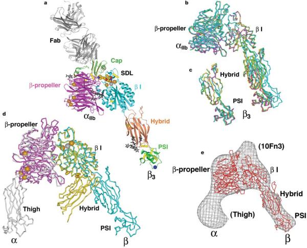
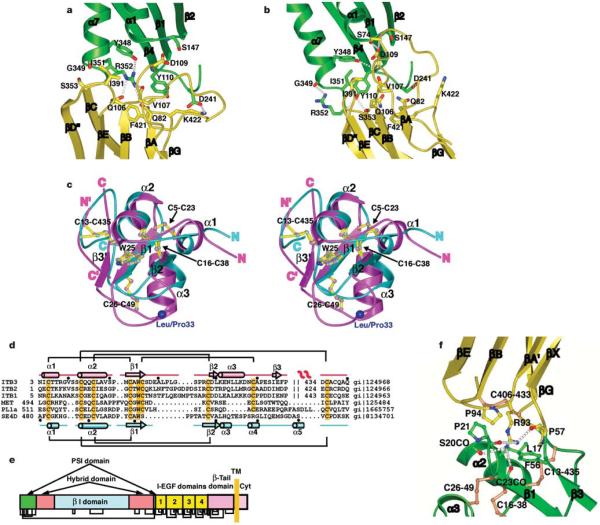
Integrins are important adhesion receptors in all Metazoa that transmit conformational change bidirectionally across the membrane. Integrin alpha and beta subunits form a head and two long legs in the ectodomain and span the membrane. Here, we define with crystal structures the atomic basis for allosteric regulation of the conformation and affinity for ligand of the integrin ectodomain, and how fibrinogen-mimetic therapeutics bind to platelet integrin alpha(IIb)beta3. Allostery in the beta3 I domain alters three metal binding sites, associated loops and alpha1- and alpha7-helices. Piston-like displacement of the alpha7-helix causes a 62 degrees reorientation between the beta3 I and hybrid domains. Transmission through the rigidly connected plexin/semaphorin/integrin (PSI) domain in the upper beta3 leg causes a 70 A separation between the knees of the alpha and beta legs. Allostery in the head thus disrupts interaction between the legs in a previously described low-affinity bent integrin conformation, and leg extension positions the high-affinity head far above the cell surface.


Figures

Figure 1
Figure 1
Quaternary rearrangements in the integrin ectodomain. a–c, Three conformational states visualized in electron microscopy, and in crystal structures (here and in ref. 7). d–j, Proposed intermediates in equilibration between known conformational states. The upper pathways may be stimulated by ligand binding outside the cell, and the lower pathways by signals within the cell that separate the α and β subunit transmembrane domains. Domains in a–j are shown in solid colour if known directly from crystal structures, dashed with grey if placed from crystal structures into electron microscopy image averages, and in solid grey for EGF-1 and EGF-2, which are modelled on EGF-3 and EGF-4.
Figure 2
Figure 2
Structure of the αIIbβ3 headpiece. a, Ribbon diagram of the αIIbβ3:10E5 complex. Calcium and magnesium ions are shown as gold and silver spheres, respectively. Tirofiban is shown in cpk. The Cα atom of HPA-1a alloantigenic determinant Leu 33 in the PSI domain is shown as a blue sphere. Glycan chains are displayed as black sticks. Integrin disulphides are shown as yellow Cα –Ca bonds. b, Superimposed on the basis of the β I domain are the three independent αIIbβ3 heterodimers in crystal form B (magenta, green and yellow), and one in form A (cyan). c, The hybrid and PSI domains of the four independent αIIbβ3 structures are superimposed. d, Liganded-open αIIbβ3 (crystal form A) and unliganded-closeda αVβ3 headpieces are superimposed using the β I domainb -sheet. The α and β subunits are coloured magenta and cyan in αIIbβ3 and grey and yellow in αVβ3. Calcium and magnesium ions inαIIbβ3 only are gold and silver spheres, respectively. Yellow cylinders in the β I/hybrid interface show positions of residues where introduction of N-glycosylation sites induces high affinity for ligand and LIBS epitope exposure,. e, Superposition of an αIIbβ3 structure from crystal form B (red Cα-trace) on the three-dimensional electron microscopy density (grey chickenwire) of the fibronectin-bounda β5β1 headpiece. Domains are labelled and those only in the α5b1 structure including the tenth FN3 domain of fibronectin are in parentheses. Figures in this paper utilize crystal form A unless stated otherwise and were prepared with programs Bobscript, Povray (The Povray Team, http://www.povray.org), Raster3D and Ribbons.
Figure 3
Figure 3
The binding sites for ligand-mimetic antagonists and fibrinogen at the α/β subunit interface. a, Mapping of fibrinogen binding sensitive mutations,, in αIIbβ3. Cβ atoms of fibrinogen-binding sensitive residues are shown as spheres in the same colour as the domains in which they are present. The tirofiban-bound structure is shown. b–f, Binding of ligands or pseudoligands to αIIbβ3 (b–e) and binding of (f) cyclo Arg-Gly-Asp-D-Phe-N-methyl-Val (cyclo RGDfV) to αVβ3 (ref. 8). The orientation is identical to that in a. The α and β subunits are shown in magenta and cyan, respectively. Small molecules are shown as ball-and-stick models with their carbon, nitrogen, oxygen, sulphur and arsenic atoms coloured yellow, blue, red, green and grey, respectively. Hydrogen bonds are shown as dotted lines. Ca2+ and Mg2+ ions are gold and silver spheres, respectively. The ligand and S123 coordinations to the MIDAS metal are shown as thin grey lines.
Figure 4
Figure 4
Allostery in theb I domain and comparison with α I domain. a, Overview of motions in the β3 I and hybrid domains. Non-moving parts of the backbone are shown as a grey worm. Moving segments shown as Cα-traces are from unliganded-closed αVβ3 (gold), liganded-closed αVβ3 (magenta) and liganded-open αIIbβ3 (cyan). The direction of movement is shown with arrows. b, Comparison witha I domains. The moving segments of unliganded-closed (gold) and pseudoliganded-open (cyan) αM I domains, and their MIDAS metal ions are shown as in a and in the same orientation. c, Hydrophobic ratchet pockets underlying the β6–α 7 loop anda 1-helix. The unliganded-closed (orange) and liganded open (cyan) β 1–α 1 loop, α 1-helix, α 1–b 2 loop and β 6–α 7 loop anda 7-helix are shown as worm traces with key side chains, the Met 335 carbonyl and metal ions in the same colour. The rest of the domain is shown as a grey surface, except for hydrophobic pocket residues Tyr 116, Val 247, Thr 249, Ile 307, Ala 309 and Thr 311, which are shown as a black surface. d3 I domain metal coordination sites in liganded-open αIIbβ3 (cyan) and unliganded-closed αVβ3 (yellow). LIMBS, MIDAS and ADMIDAS positions are shown left to right in similar orientation as in a. The LIMBS and MIDAS were not occupied in the unliganded-closed structure; for reference, metal ions at these sites are shown from the liganded-closed structure. In a–d, metal ions are shown as spheres in the same or a similar (d) colour as their associated backbone. e, Distances between Ca atoms in the three superimposed β I domains, smoothed by averaging at each residue over a 3-residue window.
Figure 5
Figure 5
The hybrid and PSI domains and their interfaces. a, b, The β I/hybrid domain interface in the unliganded-closed structure (a) and liganded-open structure (b). Ribbon backbone and side-chain carbon atoms are shown in green (β I) and yellow (hybrid) with theb I domainb β-sheet in the same orientation. The α7-helical ribbon is shown up to the same residue (350) in both structures to aid comparison of α7-helix position. c, Stereo view of the superposition of the PSI domains fromβ3 (magenta) and semaphorin4D (cyan). The disulphide bridges and the conserved tryptophan are shown as ball-and-stick models with their bonds coloured yellow and atoms the same colour as the backbone. The Leu/Pro 33 alloantigen site is represented with a large blue Ca sphere. The amino and carboxyl termini of each domain are indicated. The N’ and C’ refer to termini for residues 434–440 that constitute part of the PSI and EGF-1 domains. d, Sequence alignment of PSI domains from integrins, semaphorin4D (SE4D), a plexin and c-met. Disulphide connections are shown above (β3) and below (semaphorin4D) the respective sequences. The conserved cysteines and tryptophans are highlighted orange. The secondary structures are shown for β3 (top) and sema4D (bottom). e, Domain organization of integrin β subunits, showing multiple domain insertions. The revised disulphide bond pattern is shown below. f, The interface between the hybrid (yellow) and PSI (green) domains. Disulphide bonds are shown in orange.

Comment in

  • Cell biology: adhesion articulated.
    Mould AP, Humphries MJ. Mould AP, et al. Nature. 2004 Nov 4;432(7013):27-8. doi: 10.1038/432027a. Nature. 2004. PMID: 15525967 No abstract available.

References

    1. Hughes PE, Pfaff M. Integrin affinity modulation. Trends Cell Biol. 1998;8:359–364. - PubMed
    1. Takagi J, Springer TA. Integrin activation and structural rearrangement. Immunol. Rev. 2002;186:141–163. - PubMed
    1. Takagi J, Petre BM, Walz T, Springer TA. Global conformational rearrangements in integrin extracellular domains in outside-in and inside-out signaling. Cell. 2002;110:599–611. - PubMed
    1. Springer TA, Wang J.-h. In: Cell Surface Receptors. Garcia KC), editor. Elsevier; San Diego: 2004.
    1. Coller BS. Platelet GPIIb/IIIa antagonists: the first anti-integrin receptor therapeutics. J. Clin. Invest. 1997;99:1467–1471. - PMC - PubMed

Publication types

MeSH terms