. 2003 Sep 15;22(18):4646-55.
doi: 10.1093/emboj/cdg449.

Crystal structure of the M1 protein-binding domain of the influenza A virus nuclear export protein (NEP/NS2)

Affiliations

Crystal structure of the M1 protein-binding domain of the influenza A virus nuclear export protein (NEP/NS2)

Hatice Akarsu et al. EMBO J. .

Abstract

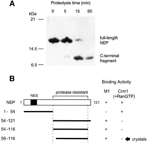
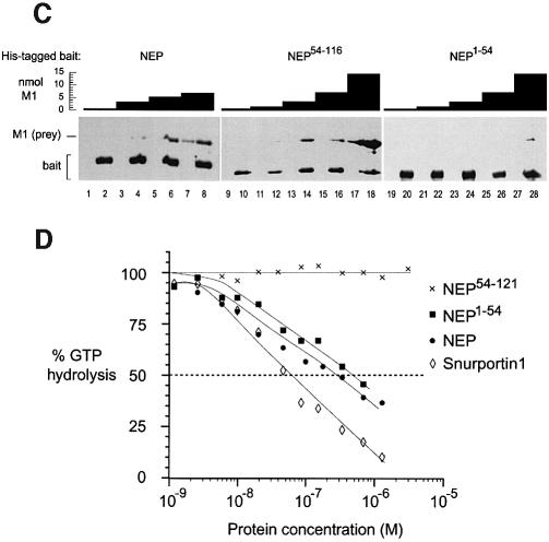
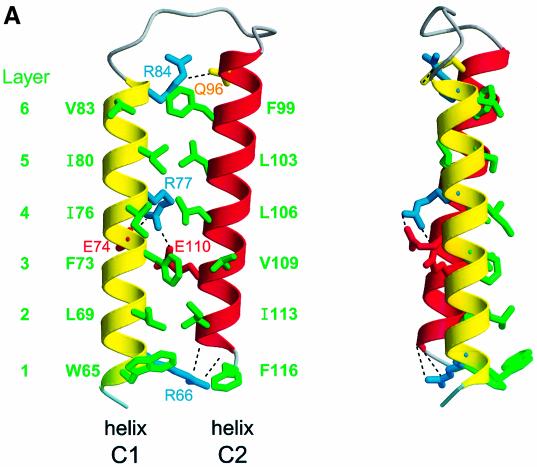
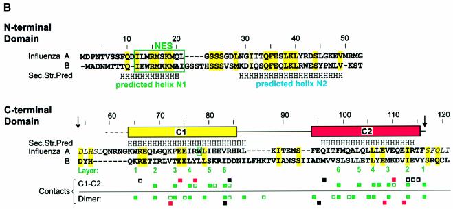
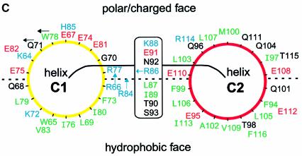
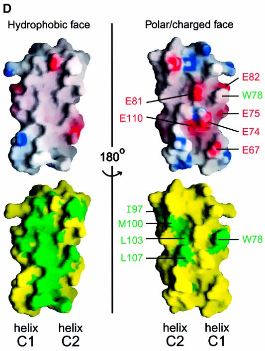
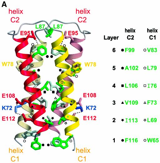
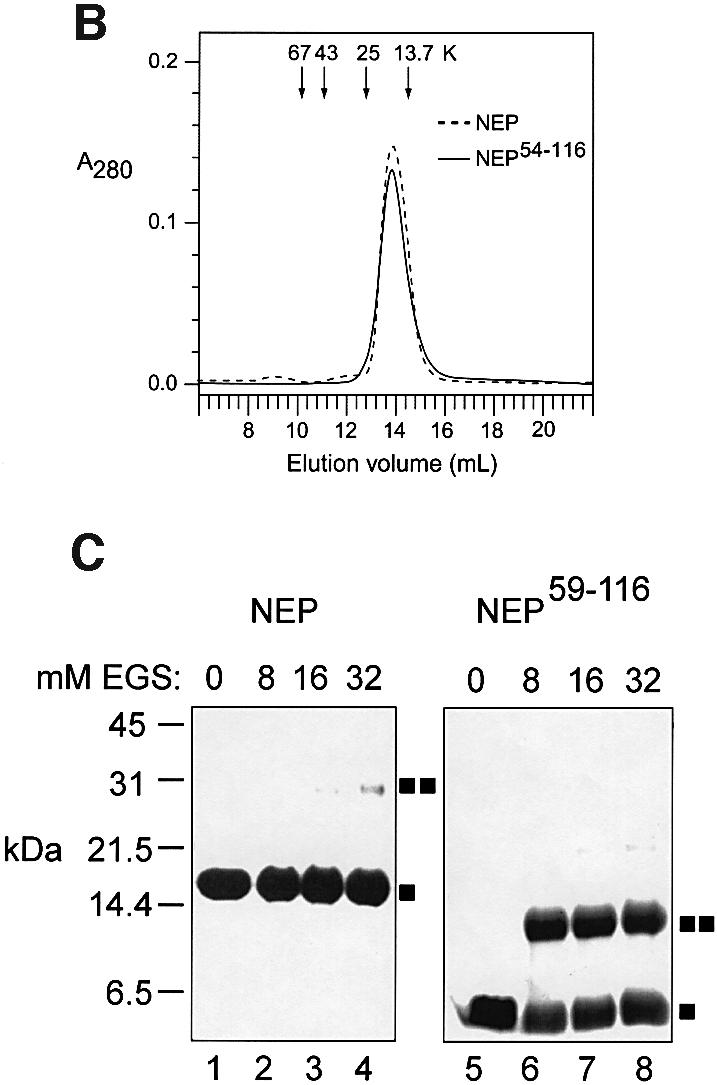
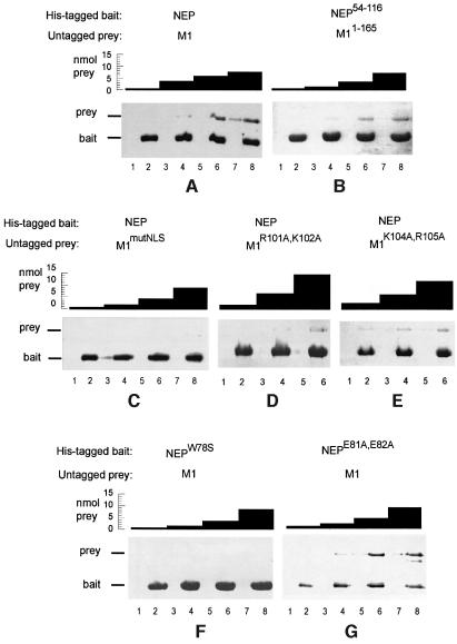
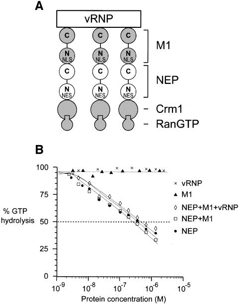
During influenza virus infection, viral ribonucleoproteins (vRNPs) are replicated in the nucleus and must be exported to the cytoplasm before assembling into mature viral particles. Nuclear export is mediated by the cellular protein Crm1 and putatively by the viral protein NEP/NS2. Proteolytic cleavage of NEP defines an N-terminal domain which mediates RanGTP-dependent binding to Crm1 and a C-terminal domain which binds to the viral matrix protein M1. The 2.6 A crystal structure of the C-terminal domain reveals an amphipathic helical hairpin which dimerizes as a four-helix bundle. The NEP-M1 interaction involves two critical epitopes: an exposed tryptophan (Trp78) surrounded by a cluster of glutamate residues on NEP, and the basic nuclear localization signal (NLS) of M1. Implications for vRNP export are discussed.


Figures

None
Fig. 1. Proteolysis of NEP defines two functionally distinct domains. (A) Proteolytic time course. NEP was incubated with elastase in a 1000:1 molar ratio at 20°C. The reaction was stopped with 1 mM phenylmethylsulfonyl fluoride (PMSF) at the times shown. (B) Summary of deletion mutants. Fragment NEP59–116 was obtained by subtilisin cleavage of NEP54–116. (C) The C-terminal domain of NEP mediates binding to M1. Nickel–agarose beads preincubated with a His-tagged NEP construct (‘bait’) (even-numbered lanes) or buffer (odd-numbered lanes) were incubated with the indicated amounts of untagged M1 (‘prey’). After washing, bound proteins were eluted and analyzed by denaturing gel electrophoresis. (D) The N-terminal domain of NEP mediates RanGTP-dependent binding to Crm1. Ran-[γ-32P]GTP and Crm1 were incubated with various concentrations of snurportin1 or an NEP construct. The GTPase reaction was initiated by addition of RanGAP and hydrolysis of Ran-bound GTP was determined as 32P release. Both NEP and NEP1–54, but not NEP54–121, bound cooperatively with RanGTP to Crm1, causing a decrease in GTP hydrolysis. Data points represent the mean of three independent measurements, and in all cases the standard deviation did not exceed 10% of the mean value.
None
Fig. 2. Structure of the NEP C-terminal domain. (A) Ribbon diagram. The six layers of hydrophobic residues involved in interhelical contacts are shown. Also shown are the hydrogen bond between Arg84 and Gln96, the capping interaction between Arg66 and the C-terminus of helix C2, and the salt bridge involving Arg77, Glu74 and Glu110. For clarity, not all interhelical contacts are shown. (B) Sequence and secondary structure of NEP. Residues conserved between influenza A and B viruses are highlighted in yellow and grey. Residues predicted by the program PHD to be helical with >90% probability are labelled H. The NES motif and residue Trp78 implicated in M1 binding are boxed. Arrows mark limits of the proteolytically resistant fragment; residues in italics are absent from the construct used for structure determination; disordered residues are indicated by the dotted line. Contacts between helices C1 and C2 within one monomer, and those between two monomers of the dimer are indicated as follows: green squares, van der Waals contact involving a hydrophobic residue (filled square) or the aliphatic moiety of a polar residue (empty square); red square, salt bridge; filled black square, hydrogen bond; empty black square, capping interaction of Arg66 with C-terminus of helix C2. Typically, residues from helix C1 interact with those from helix C2 of the same or an adjacent layer. (C) Schematic diagram showing side-chain distribution. Helix C1 is viewed from C- to N-terminus and helix C2 from N- to C-terminus. Hydrophobic, polar, acidic and basic residues are coloured green, black, red and blue, respectively. The side chains of Arg66 and Arg84 emerge from the polar/charged face; those of Gln71, Trp78 and Arg86 point as shown by the arrows. (D) Surface properties of the C-terminal domain. Upper panels: electrostatic surface potential plotted from –10 kT (red) to +10 kT (blue). Lower panels: distribution of hydrophobic (green) and hydrophilic (yellow) side chains. The upper and lower left panels are in the same orientation as (A). The figure was produced using GRASP (Nicholls et al., 1991).
None
Fig. 3. The NEP C-terminal domain dimer. (A) Ribbon diagram of the four-helix bundle. The two monomers belong to the same asymmetric unit, related by a non-crystallographic dyad running nearly parallel to the individual helices. Six successive layers of interacting side chains define the hydrophobic core. Each of the helices in the bundle contributes one or more side chains per layer, with symmetry-related residues in the same layer. Not all residues in the dimerization interface are shown (but see Figure 2B). Hydrophobic residues in the dimer interface are identified in the legend to the right. Also shown are residue Trp78 implicated in M1 binding, the hydrogen bond between Glu95 and the backbone carbonyl of Val83, and the salt bridge involving Lys72, Glu108 and Glu112. (B) Analytical gel filtration of NEP and NEP54–121. Arrows (from left to right) indicate elution volumes of the globular reference proteins bovine serum albumin, ovalbumin, chymotrypsinogen A and RNase A. The elution volumes of NEP (14.5 kDa) and NEP54–121 (8.5 kDa) are nearly identical, suggesting that the latter is a dimer in solution. (C) Cross-linking experiment. NEP or NEP59–116 was incubated with the indicated amount of EGS for 1 h on ice. Reactions were quenched by adding 100 mM Tris and analyzed by denaturing gel electrophoresis. Squares indicate the positions of monomers and dimers. Small amounts of the dimeric NEP and tetrameric NEP59–116 species at high EGS concentrations are probably due to transient interactions between molecules in solution.
None
Fig. 4. NEP residue Trp78 and the NLS of M1 mediate NEP–M1 binding. Nickel–agarose beads preincubated with a His-tagged NEP construct (‘bait’) (even-numbered lanes) or buffer (odd-numbered lanes) were incubated with the indicated amounts of untagged M1 or an M1 mutant (‘prey’). After washing, bound proteins were eluted and analyzed by denaturing gel electrophoresis. (A) NEP binds to M1. (B) The C-terminal NEP domain binds to the N-terminal domain of M1. (C) Mutation of the NLS motif in M1 severely reduces binding to NEP. (D) Mutation of R101 and K102 residues in M1 reduces binding to NEP. (E) Mutation of K104 and R105 residues in M1 reduces binding to NEP. (F) Mutation of NEP residue Trp78 disrupts binding to M1. (G) Mutation of NEP residues Glu81 and Glu82 has little effect on binding to M1.
None
Fig. 5. Possible interactions among influenza viral components. (A) A hypothetical export complex. Crm1/RanGTP binds to NEP, NEP binds to M1 and M1 binds to vRNP. The binding surfaces involved in the individual interactions are spatially distinct. The N- and C-terminal domains and NLS and NES motifs of M1 and NEP are indicated. A single vRNP may recruit several molecules of Crm1. (B) RanGTPase assay involving several viral components. The assay was performed essentially as for Figure 1D. NEP, but not M1 or vRNP, binds to Crm1 cooperatively with RanGTP. NEP preincubated with an equimolar amount of M1 or with M1 plus vRNP behaves similarly to NEP alone.

References

    1. Arzt S., Baudin,F., Barge,A., Timmins,P., Burmeister,W.P. and Ruigrok,R.W.H. (2001) Combined results from solution studies on intact influenza virus M1 protein and from a new crystal form of its N-terminal domain show that M1 is an elongated monomer. Virology, 279, 439–446. - PubMed
    1. Askjaer P., Heick Jensen,T., Nilsson,J., Engelmeier,L. and Kjems,J. (1998) The specificity of the CRM1-Rev nuclear export signal interaction is mediated by RanGTP. J. Biol. Chem., 273, 33414–33422. - PubMed
    1. Baudin F., Bach,C., Cusack,S. and Ruigrok,R.W.H. (1994) Structure of influenza RNP.I. Influenza virus nucleoprotein melts secondary structure in panhandle RNA and exposes the bases to solvent. EMBO J., 13, 3158–3165. - PMC - PubMed
    1. Baudin F., Petit,I., Weissenhorn,W. and Ruigrok,R.W.H. (2001) In vitro dissection of the membrane binding and RNP binding activities of influenza virus M1 protein. Virology, 281, 102–108. - PubMed
    1. Bischoff F.R., Krebber,H., Smirnova,E., Dong,W. and Ponstingl,H. (1995) Co-activation of RanGTPase and inhibition of GTP dissociation by Ran-GTP binding protein RanBP1. EMBO J., 14, 705–715. - PMC - PubMed

MeSH terms

Associated data