. 2020 May 1;295(18):5944-5959.
doi: 10.1074/jbc.RA120.012697. Epub 2020 Mar 16.

Structure-based discovery of a small-molecule inhibitor of methicillin-resistant Staphylococcus aureus virulence

Affiliations

Structure-based discovery of a small-molecule inhibitor of methicillin-resistant Staphylococcus aureus virulence

Jie Liu et al. J Biol Chem. .

Abstract

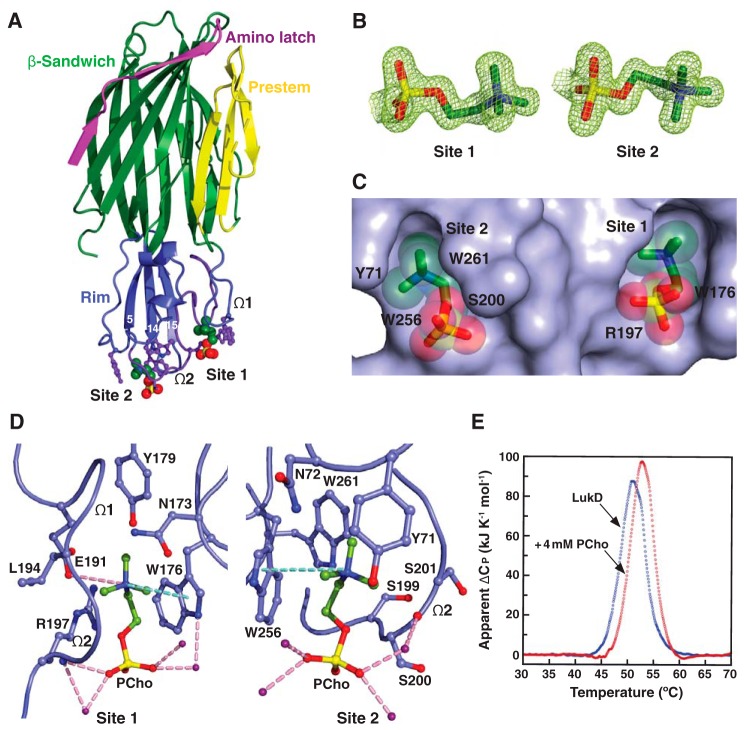
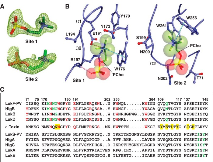
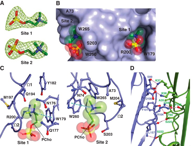
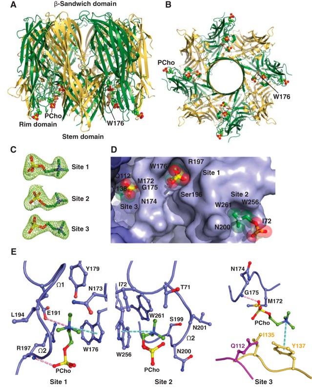
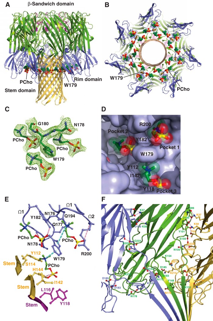
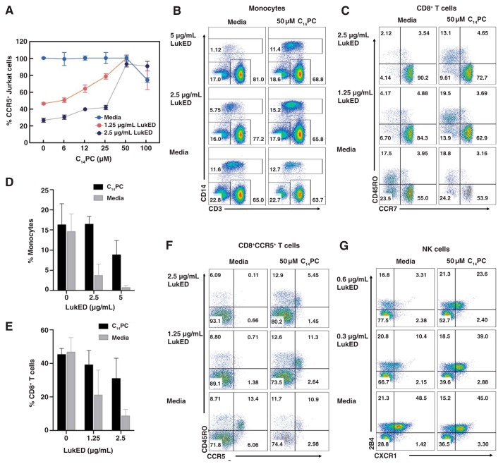
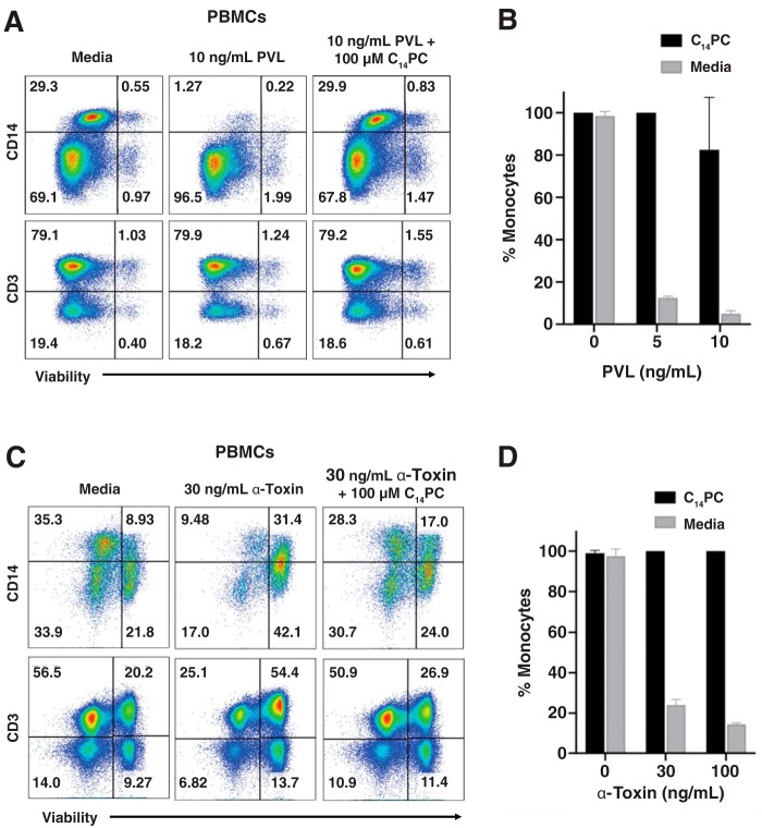
The rapid emergence and dissemination of methicillin-resistant Staphylococcus aureus (MRSA) strains poses a major threat to public health. MRSA possesses an arsenal of secreted host-damaging virulence factors that mediate pathogenicity and blunt immune defenses. Panton-Valentine leukocidin (PVL) and α-toxin are exotoxins that create lytic pores in the host cell membrane. They are recognized as being important for the development of invasive MRSA infections and are thus potential targets for antivirulence therapies. Here, we report the high-resolution X-ray crystal structures of both PVL and α-toxin in their soluble, monomeric, and oligomeric membrane-inserted pore states in complex with n-tetradecylphosphocholine (C14PC). The structures revealed two evolutionarily conserved phosphatidylcholine-binding mechanisms and their roles in modulating host cell attachment, oligomer assembly, and membrane perforation. Moreover, we demonstrate that the soluble C14PC compound protects primary human immune cells in vitro against cytolysis by PVL and α-toxin and hence may serve as the basis for the development of an antivirulence agent for managing MRSA infections.

Keywords: MRSA; Panton-Valentine leukocidin (PVL); alpha-toxin; antivirulence therapy; drug discovery; leukocidin ED (LukED); methicillin-resistant Staphylococcus aureus (MRSA); phosphatidylcholine; pore-forming toxin; structural biology; structure-based drug design; toxin; virulence factor.


Conflict of interest statement

The authors declare that they have no conflicts of interest with the contents of this article

Figures

Figure 1.
Figure 1.
Structural basis for C14PC binding to LukD. A, cocrystal structure of C14PC bound to LukD shown from a side view perpendicular to the membrane plane, with the PCho moieties and the side chains of key binding site residues displayed as CPK spheres and in ball-and-stick format, respectively. The amino latch (magenta) and prestem (yellow) regions and the β-sandwich (green) and rim (blue) domains are indicated. The two binding sites are labeled, as are the β-strands that compose the rim domain and the Ω1 and Ω2 loops. B, 2FoFc omit electron density map (green mesh) for the two PCho moieties at 1.5σ contour level. C, surface representation of the C14PC-LukD complex viewed parallel to the membrane, with the PCho moieties shown in stick format with transparent CPK spheres. The locations of key binding site residues are indicated. D, close-up view of the two adjacent PCho binding pockets, with residues that make direct side-chain contacts with the PCho moieties shown in ball-and-stick format. Cation-π interactions are represented as green dotted lines. Hydrogen bonds and salt bridges are shown as pink dotted lines, and water molecules are shown as purple spheres. E, DSC thermograms of LukD in the absence (Tm = 51.0 °C) and presence (Tm = 52.8 °C) of PCho.
Figure 2.
Figure 2.
Structure of C14PC-bound Luk-PV. A, 2FoFc electron density map shown as green mesh around the two PCho moieties contoured at 1.5σ (site 1) and 1.0σ (site 2). B, molecular interactions in the C14PC-LukF-PV complex, with the PCho moieties shown in stick format with transparent CPK spheres. The side chains of residues that make direct contacts with the PCho moieties are shown in ball-and-stick format. The two binding sites and the Ω1 and Ω2 loops are labeled. Cation-π interactions are represented as green dotted lines. Hydrogen bonds and salt bridges are shown as pink dotted lines. C, sequence alignment for members of the α-hemolysin toxin subfamily around the regions of the three PCho-binding sites (see “Results” for details). Four segments of the rim domain (residues 71–75, 170–180, 191–202, and 255–264) and two segments of the stem domain (residues 109–117 and 137–145) are delineated by spaces and numbered according to the mature LukF-PV protein. Conserved residues at the two binding sites on the rim domain are highlighted in red. Conserved residues that constitute the interprotomer binding sites on the PVL heterooctamer and the α-toxin heptamer are highlighted with a green and yellow background, respectively.
Figure 3.
Figure 3.
The two adjacent PC-binding pockets on monomeric α-toxinH35A. A, 2FoFc electron density map (green mesh) for the two PCho moieties contoured at 1.2σ (site 1) and 1.0σ (site 2). B, surface representation of the C14PC-α-toxinH35A complex viewed parallel to the membrane, with the PCho moieties shown in stick format with transparent CPK spheres. The two binding sites are labeled. The locations of key binding site residues are indicated. C, close-up view of the two adjacent PCho-binding pockets, with the PCho moieties displayed in stick format with transparent CPK spheres. Residues that make direct side chain contacts with the PCho moieties are shown in ball-and-stick format. The Ω1 and Ω2 loops are labeled. Cation-π interactions are represented as green dotted lines. Hydrogen bonds are shown as pink dotted lines. D, close-up view of the interface between the two independent α-toxinH35A monomers (blue and green, respectively) in the asymmetric unit. Hydrogen bonds and salt bridges near the His35→Ala mutation site are depicted as pink dotted lines.
Figure 4.
Figure 4.
Crystal structure of C14PC in complex with the PVL heterooctamer. A and B, ribbon representation of the C14PC-bound PVL heterooctamer shown from the side (A) and cytoplasmic (B) views. The PCho moieties and the side chain of Trp176 are displayed as CPK spheres and in stick format, respectively. The LukF-PV and LukS-PV subunits are colored green and yellow, respectively. The β-sandwich, rim, and stem domains are indicated. C, 2FoFc omit electron density map contoured at 1.0σ shown as green mesh around the three PCho moieties in a single protomeric unit. D, surface representation of the three PCho-binding pockets on a single protomeric unit viewed from the cytoplasmic side, with the PCho moieties shown in stick format with transparent CPK spheres. The three binding sites are labeled. The locations of key binding site residues are indicated. E, close-up view of the PCho moieties in the three binding pockets on a single protomeric unit. The side chains of residues that make direct contacts with the PCho moieties are shown in ball-and-stick format colored in blue for protomer A, in magenta for protomer G, and in yellow for protomer H. The Ω1 and Ω2 loops are labeled. Cation-π interactions are depicted as green dotted lines. Hydrogen bonds and salt bridges are represented as pink dotted lines.
Figure 5.
Figure 5.
Structure of C14PC bound to the α-toxin heptamer. A and B, ribbon representation of C14PC in complex with α-toxin heptamer shown from the side (A) and cytoplasmic (B) views. The PCho moieties and the side chain of Trp179 are shown as CPK spheres and in stick format, respectively. The amino latch region and the β-sandwich, rim, and stem domains are colored as in Fig. 1A. C, 2FoFc electron density map (green mesh) contoured at 1.0σ for residues Asn178, Trp179, and Gly180 and the three PCho moieties in a single protomeric unit. D, surface representation of the three partially overlapping PCho-binding pockets on a single protomeric unit viewed from the cytoplasmic side, with PCho moieties shown in stick format with transparent CPK spheres. The three binding pockets are labeled. The locations of key binding site residues are indicated. E, molecular interactions in the heptameric α-toxin-C14PC complex, with the PCho moieties in a single protomeric unit displayed in ball-and-stick format. Residues that make direct side-chain contacts with the PCho moieties are shown in ball-and-stick format colored in blue for protomer A, in purple for protomer E, and in yellow for protomer F. The Ω1 and Ω2 loops are labeled. Cation-π interactions are represented as green dotted lines. Hydrogen bonds and salt bridges are shown as pink dotted lines. F, close-up view of interprotomer interactions in the triangle region in the crystal structure of the C14PC-bound α-toxinH35A heptamer. Protomers A, B, and C are colored blue, green, and yellow, respectively.
Figure 6.
Figure 6.
C14PC protects target cells from lysis by LukED. A, titration of the cytotoxicity of LukED by C14PC. CCR5+ Jurkat cells were challenged with different concentrations of LukED in the absence and presence of C14PC (6–100 μm). Cell viability was determined by flow cytometry and normalized to that in the medium control. Data are representative of at least three independent experiments, and values are expressed in the mean of triplicate measurements ± S.E. B, protective effect of C14PC against LukED-mediated killing of primary human monocytes. PBMCs were challenged with LukED in the presence and absence of 50 μm C14PC. Monocyte subsets were identified as CD3CD14+ after gating on live PBMCs as determined by flow cytometry. Data are representative of two independent experiments. Percentages of cells in each quadrant are indicated. C, protective effect of C14PC against LukED-mediated killing of CD8+ effector memory T cells (CCR7CD45RO+ and CCR7CD45RO). PBMCs were challenged with LukED in the presence and absence of 50 μm C14PC. Live CD3+CD8+ T cell subsets were gated and analyzed for the expression of CCR7 and CD45RO by flow cytometry. Data are representative of two independent experiments using blood from different donors. D and E, bar graphs showing inhibition of the LukED-induced lysis of monocytes (D) and CD8+ effector memory T cells (E) by 50 μm C14PC. Error bars, S.E. F, protective effect of C14PC against LukED-mediated killing of CD8+CCR5+ T cells. PBMCs were challenged with LukED in the presence and absence of 50 μm C14PC. Live CD3+CD8+ T cell subsets were gated and analyzed for the expression of CCR5 and CD45RO by flow cytometry. Data are representative of two independent experiments. G, protective effect of C14PC against LukED-mediated killing of NK cells. PBMCs were challenged with LukED in the presence and absence of 50 μm C14PC. PBMCs were first gated on live CD3HLA-DR cells, and the proportion of CXCR1+2B4+ NK cells was analyzed by flow cytometry. Data are representative of two independent experiments.
Figure 7.
Figure 7.
C14PC protects primary human monocytes from lysis by both PVL and α-toxin. A, protective effect of C14PC against PVL-mediated killing of monocytes. PBMCs were challenged with PVL in the presence and absence of 100 μm C14PC. Monocyte subsets were gated based on the forward scatter and side scatter parameters and then analyzed for the expression of CD14+ and CD3+, respectively. Cell viability was determined by flow cytometry and normalized to that in the medium control. Data are representative of two independent experiments using blood from different donors. Percentages of cells in each quadrant are indicated. B, bar graph showing inhibition of the PVL-induced lysis of monocytes by 100 μm C14PC. Error bars, S.E. C, protective effect of C14PC against α-toxin–mediated killing of monocytes. PBMCs were challenged with α-toxin in the presence and absence of 100 μm C14PC. Monocyte subsets were identified and quantified as described in A. Data are representative of two independent experiments using blood from different donors. D, bar graph showing inhibition of the α-toxin–induced lysis of monocytes by 100 μm C14PC. Error bars, S.E.

References

    1. Lowy F. D. (1998) Staphylococcus aureus infections. N. Engl. J. Med. 339, 520–532 10.1056/NEJM199808203390806 - DOI - PubMed
    1. Klevens R. M., Morrison M. A., Nadle J., Petit S., Gershman K., Ray S., Harrison L. H., Lynfield R., Dumyati G., Townes J. M., Craig A. S., Zell E. R., Fosheim G. E., McDougal L. K., Carey R. B., et al. (2007) Invasive methicillin-resistant Staphylococcus aureus infections in the United States. JAMA 298, 1763–1771 10.1001/jama.298.15.1763 - DOI - PubMed
    1. Otto M. (2010) Basis of virulence in community-associated methicillin-resistant Staphylococcus aureus. Annu. Rev. Microbiol. 64, 143–162 10.1146/annurev.micro.112408.134309 - DOI - PubMed
    1. Chambers H. F., and Deleo F. R. (2009) Waves of resistance: Staphylococcus aureus in the antibiotic era. Nat. Rev. Microbiol. 7, 629–641 10.1038/nrmicro2200 - DOI - PMC - PubMed
    1. Jones S. M., Morgan M., Humphrey T. J., and Lappin-Scott H. (2001) Effect of vancomycin and rifampicin on meticillin-resistant Staphylococcus aureus biofilms. Lancet 357, 40–41 10.1016/S0140-6736(00)03572-8 - DOI - PubMed

Publication types

MeSH terms